
Battery charge current is the electrical current flowing into a battery while it is being recharged, measured in amperes or amps. The correct setting is not automatically 10%, 0.5C or the charger’s maximum output. It must stay within the battery manufacturer’s recommendation, BMS limit, charger capability, temperature range and installation limits.
For many stationary LiFePO4 systems, 0.2C to 0.5C is a useful preliminary design range, while many deep-cycle lead-acid systems are commonly designed around approximately 0.1C to 0.2C. These are starting points rather than universal settings. The battery datasheet and system design must take priority.
What Is Battery Charge Current?
Battery charge current is the rate at which electrical charge enters a rechargeable battery. It is normally shown in amperes, while battery capacity is shown in amp-hours. Current determines how quickly charge is added, but voltage, chemistry, temperature, state of charge and BMS control determine whether the battery can safely accept it.
A 100Ah battery receiving 20A is being charged at 0.2C. A 280Ah battery receiving 100A is being charged at approximately 0.36C.
Charging current should not be confused with voltage, power or capacity.
| Parameter | What it Describes | Unit | Battery Example |
|---|---|---|---|
| Voltage | Electrical potential and battery platform | V | 51.2V |
| Charge current | Rate of charge entering the battery | A | 100A |
| Capacity | Amount of electrical charge the battery can store | Ah | 280Ah |
| Energy | Capacity after voltage is included | Wh or kWh | About 14.3kWh at 51.2V and 280Ah |
| Charging power | Rate of energy transfer | W or kW | 51.2V × 100A = 5.12kW |
| C-rate | Current relative to battery capacity | C | 100A ÷ 280Ah = 0.36C |
For a more detailed explanation of these electrical terms, see Avepower’s guides to voltage vs current and battery capacity in Ah, Wh and kWh.
Need Help Matching Battery Charge Current With Your Solar System?
Choosing the correct charging current requires matching battery capacity, inverter power, BMS limits and daily energy requirements. Avepower helps installers select suitable LiFePO₄ battery configurations for residential and commercial energy storage projects.
Get expert support for battery sizing, charging parameters and inverter compatibility.
→ Request a Battery Solution Consultation
What Is the Relationship Between Battery Charge Current and C-rate?
Battery charge current and C-rate describe the same charging behavior from different perspectives.
C-rate represents charging current relative to battery capacity. A 1C charging rate means a battery could theoretically be charged in approximately one hour under ideal conditions.
Example:
| Battery Capacity | 0.5C Charging Current | 1C Charging Current |
|---|---|---|
| 50Ah | 25A | 50A |
| 100Ah | 50A | 100A |
| 200Ah | 100A | 200A |
| 314Ah | 157A | 314A |
For most residential and commercial LiFePO₄ energy storage systems, 0.5C charging is commonly selected because it provides a balance between charging speed, heat control, and battery lifespan.
Avepower’s battery C-rate guide explains how the same formula applies to charging and discharging while the permitted values can remain very different.
What Is the Correct Charging Current for a Battery?
The correct battery charging current is the lowest safe value produced by the complete system assessment. It should meet the required recharge time without exceeding the battery’s recommended current, BMS charge-current limit, charger rating, source power, conductor capacity or temperature-dependent limit.
The BMS limit can change during operation. A setting that is acceptable at 25°C and 40% SOC may be reduced when the battery is cold, nearly full, poorly balanced or reporting an alarm.
Recommended Charging Current for LiFePO4 Batteries
| Battery Capacity | Typical Recommended Charge Current | Application |
|---|---|---|
| 100Ah | 30–50A | Small backup systems |
| 200Ah | 50–100A | Residential storage |
| 280Ah | 100–140A | High-capacity ESS |
| 314Ah | 100–150A | Commercial and solar storage |
A slower charging current can improve thermal performance, while higher charging current is useful when faster energy recovery is required.
What Charging Current Is Recommended for Different Battery Types?
| Battery Type | Common Preliminary Range | Charging Behaviour | Important Limitation |
|---|---|---|---|
| LiFePO4 stationary battery | Often 0.2C–0.5C | Usually CC-CV with BMS control | Check low-temperature charging and pack-level BMS limit |
| Other lithium-ion systems | Often 0.3C–1C, product-dependent | Precharge, constant current and constant voltage | Cell design, cooling and voltage accuracy are critical |
| Flooded lead-acid | Often 0.1C–0.2C | Bulk, absorption, float and sometimes equalization | Too little current or insufficient absorption can cause chronic undercharge |
| AGM | Often around 0.15C–0.25C | Multi-stage voltage-regulated charging | Sensitive to excessive voltage and heat |
| Gel lead-acid | Manufacturer-specific, commonly moderate | Controlled bulk, absorption and float | Excess current or voltage can cause gas pockets and permanent damage |
| NiMH or NiCd | Charger- and cell-specific | Current control with temperature, voltage or timer termination | Do not apply lithium or lead-acid settings |
For LiFePO4 products, 0.2C to 0.5C appears frequently in manufacturer guidance, but some batteries support higher charging rates and others impose lower limits. The appropriate current must be confirmed from the individual model’s specification.
Looking for Reliable LiFePO4 Batteries With Flexible Charge Current Options?
Avepower provides 51.2V LiFePO4 battery solutions with configurable BMS settings, CAN/RS485 communication and multiple capacity options for residential and commercial energy storage applications.
Explore battery solutions designed for installers, distributors and energy storage projects.
→ Get Wholesale Battery Pricing
What Is the Difference Between Recommended and Maximum Charge Current?
Recommended charge current is the operating value intended to balance recharge speed, heat, efficiency and service life. Maximum charge current is an upper boundary that should not be treated as the preferred everyday setting unless the manufacturer explicitly says continuous operation at that value is appropriate.
A datasheet may contain several different current ratings:
| Datasheet Term | Practical Meaning |
|---|---|
| Standard charge current | Current used for normal operation or performance testing |
| Recommended charge current | Preferred operating current under defined conditions |
| Maximum continuous charge current | Highest continuous current permitted under specified conditions |
| Peak charge current | Short-duration value, only when explicitly provided |
| BMS overcurrent threshold | Protection trip point, not a target setting |
| Charge Current Limit or CCL | Dynamic current permission sent by the BMS |
| Tail or termination current | Low current used to determine when charging is complete |
A BMS overcurrent trip value should never be used as the charger setting. Protection thresholds are designed as a final safety boundary, often with a time delay, rather than a normal operating target.
The same applies to cables and breakers. A 200A breaker does not mean the battery should be charged at 200A. Each component needs sufficient operating margin and must be coordinated with the battery documentation and applicable electrical requirements.
How Do You Calculate Battery Charge Current?
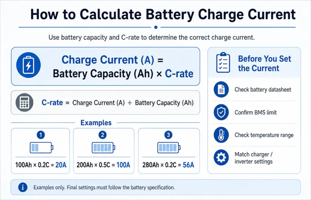
The basic formula is:
Charging Current (A) = Battery Capacity (Ah) × Charging Rate (C)
Example:
A 200Ah lithium battery:
| Charging Rate | Calculation | Charging Current |
|---|---|---|
| 0.2C | 200Ah × 0.2 | 40A |
| 0.5C | 200Ah × 0.5 | 100A |
| 1C | 200Ah × 1 | 200A |
However, the theoretical value is not always the usable value. The actual charging current must remain below:
- Cable and connector rating
- Battery manufacturer’s maximum charge current
- BMS current limit
- Charger output capability
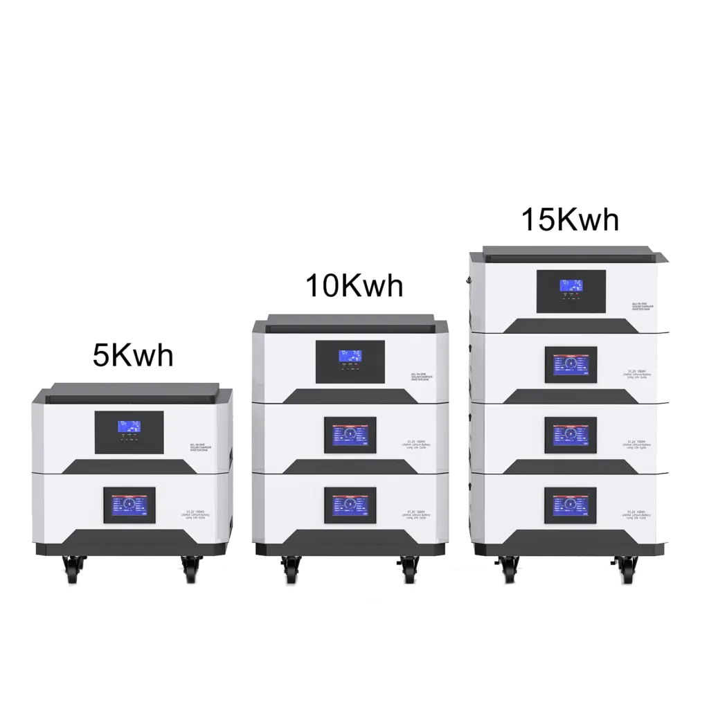
The Avepower 15kWh all-in-one solar battery illustrates this distinction: its page lists separate PV and AC charging capabilities while also specifying a lower maximum combined charging current.
What Determines the Maximum Battery Charging Current?
The maximum battery charge current is not determined only by battery capacity. Several system factors must be considered.
1. Battery Cell Capability
Different lithium cells have different charging limits.
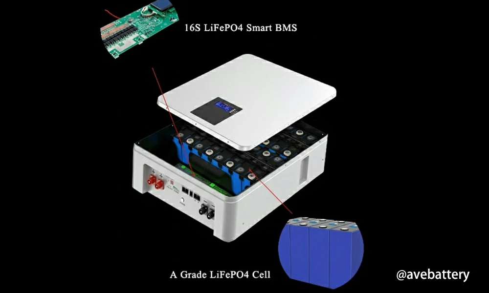
A battery using high-quality LiFePO4 cells may support higher charge rates, but the complete battery pack must still consider:
- Cell specification
- Series/parallel configuration
- Internal resistance
- Thermal design
2. Battery Management System (BMS)
The BMS acts as the protection controller.
It monitors:
- Cell voltage
- Pack current
- Temperature
- SOC
- Charging permission
If charging current exceeds the safe limit, the BMS can reduce charging power or disconnect the battery.
3. Temperature Conditions
Temperature directly affects charging performance.
Typical lithium battery operating ranges:
| Condition | Typical Range |
|---|---|
| Charging temperature | 0°C to 55°C |
| Discharging temperature | -20°C to 60°C |
Charging lithium batteries at extremely low temperatures can increase risk of lithium plating and cell damage.
4. Charger and Inverter Capability
The charger cannot provide more current than its rated output.
For example:
A 10kWh battery may support 100A charging, but if the inverter charger only outputs 60A, the actual charging current will be limited to 60A.
How Is Charge Current Calculated for Batteries in Parallel?
Parallel batteries keep approximately the same voltage while their amp-hour capacities and potential current capability increase. Theoretical bank charging current can therefore scale with the number of identical modules, but only when the manufacturer approves parallel operation and the installation supports balanced current sharing.
For four identical 100Ah batteries:
Total bank capacity = 4 × 100Ah = 400Ah
At a bank charging rate of 0.2C:
400Ah × 0.2C = 80A total
The ideal average would be:
80A ÷ 4 batteries = 20A per battery
Actual current may not divide equally.
Current sharing is affected by:
- Cable length and resistance;
- Terminal resistance;
- Battery SOC;
- Cell temperature;
- Battery age and internal resistance;
- BMS state;
- Busbar arrangement;
- Communication and master-battery control.
Use equal-length conductors, approved busbars, correctly coordinated protection and the manufacturer’s required communication configuration.
Do not assume the bank limit is always the number of batteries multiplied by one module’s maximum current. Some systems impose a lower master-BMS, inverter, communication or busbar limit.
Practical Case: What Charge Current Should a 280Ah LiFePO4 Battery Use?
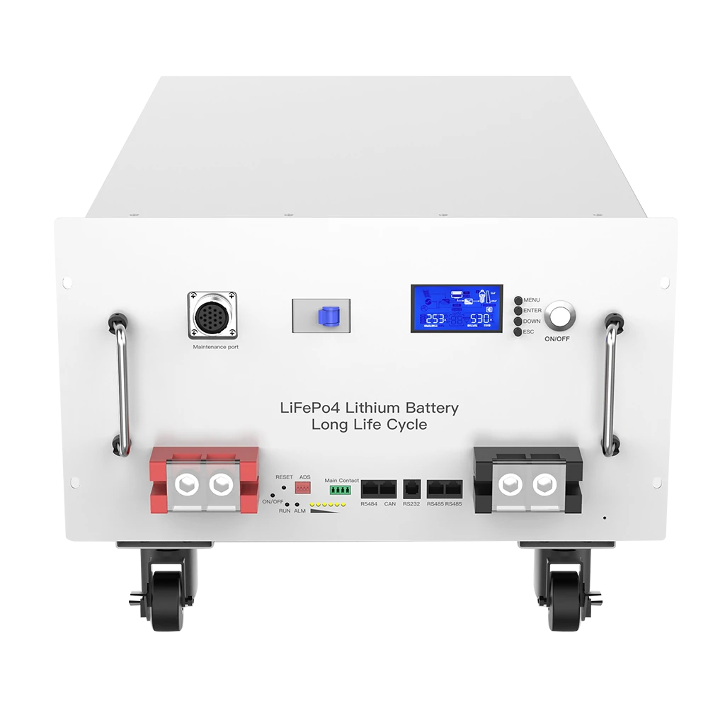
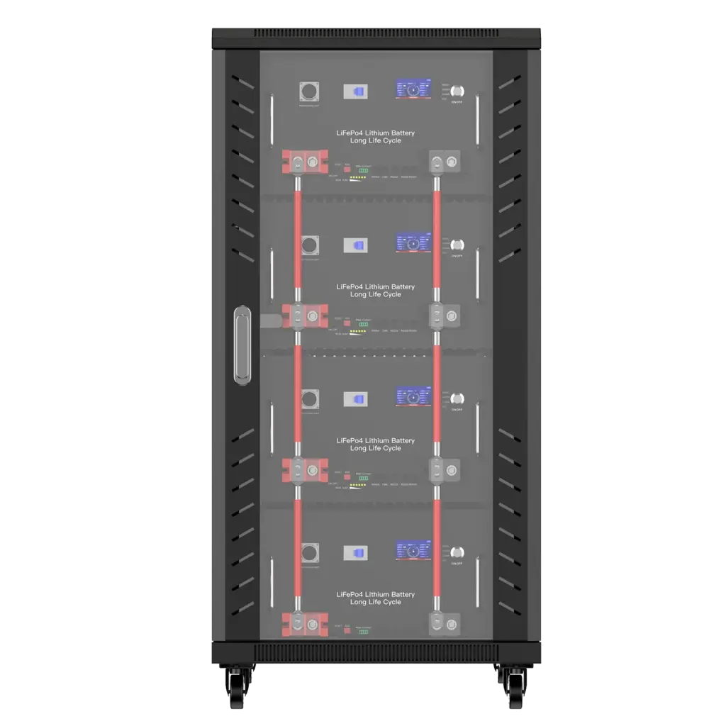
A 280Ah LiFePO4 battery should use the current stated in its product specification and the lower limit required by temperature and system conditions. For the Avepower 48V-class rack battery example, the page lists 56A under lower-temperature conditions and up to 100A under its stated higher-temperature operating condition.
The Avepower 48V 280Ah rack-mounted battery lists:
- Nominal capacity: 280Ah;
- Charge mode: CC-CV;
- Charging voltage: 58.4V;
- Standard current under the stated lower-temperature condition: 56A;
- Maximum current under the stated 10°C to 45°C condition: 100A;
- CAN, RS485 and RS232 communication;
- Support for up to 16 units in parallel.
These figures are product-specific and must be confirmed against the final project documentation and inverter configuration.
C-rate Calculation
At 56A:
56A ÷ 280Ah = 0.20C
At 100A:
100A ÷ 280Ah = 0.357C
Rounded:
100A ≈ 0.36C
Charging from 20% to 90% SOC
Required capacity:
280Ah × 70% = 196Ah
Ideal time at 56A:
196Ah ÷ 56A = 3.5 hours
Ideal time at 100A:
196Ah ÷ 100A = 1.96 hours
These are design calculations, not guaranteed field results. Actual time can be longer because of:
- Charging-current taper;
- Cell balancing;
- Charger efficiency;
- Temperature-based limits;
- BMS current requests;
- Connected loads;
- Available PV or AC power.
System Decision
Using 100A can be reasonable only when all applicable conditions permit it. A project should not set 100A merely because it appears as the maximum value.
The installer should also confirm:
- Inverter battery-voltage range;
- Maximum inverter battery-charging current;
- CAN or RS485 protocol compatibility;
- Cable and breaker selection;
- Parallel-bank configuration;
- Ambient and battery temperature;
- Battery firmware and BMS parameters.
Avepower maintains an inverter compatibility resource for project checking, but the precise inverter brand, model, firmware and communication protocol should still be confirmed before ordering or commissioning.
Build a Battery System Designed for Your Project Requirements
Every energy storage project has different requirements for charging current, capacity, communication protocols and installation environments. Avepower supports OEM/ODM customization, helping partners develop LiFePO4 battery solutions optimized for their applications.
Discuss your battery project requirements with our engineering team today.
→ Start Your Custom Battery Project
Can Battery Charging Current Be Too Low?
Charging current can be lower than the battery maximum without damaging a healthy lithium battery, but an undersized charging system may fail to restore enough energy during the available charging window. In lead-acid systems, persistent low-current charging and incomplete absorption can cause chronic undercharge and capacity loss.
Low charging current can lead to:
- Battery not reaching the target SOC before nightfall;
- Generator running for excessive periods;
- Insufficient backup reserve;
- Repeated partial-state-of-charge operation;
- Lead-acid sulfation and deficit cycling;
- Cell balancing not completing in some lithium systems;
- Poor project economics despite adequate battery capacity.
What Happens If Battery Charging Current Is Too High?
Excessive charging current can increase cell temperature, terminal heating, voltage rise and electrochemical stress. Depending on the battery design, the result may be BMS derating, overcurrent shutdown, premature aging, cell imbalance, lithium plating or a serious safety condition.
Possible signs include:
- Battery temperature rising quickly;
- BMS charge-overcurrent alarm;
- Charger repeatedly starting and stopping;
- One cell reaching high voltage much earlier than others;
- Connectors or cables becoming warm;
- Inverter reporting battery overvoltage;
- SOC rising quickly but charge ending prematurely;
- Reduced cycle performance over time.
The correct response is not to increase the BMS overcurrent threshold. First verify the battery specification, charger profile, temperature, communication and hardware design.
Why Is My Battery Charging at Fewer Amps Than Expected?
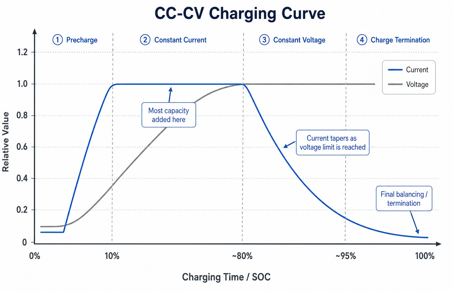
A battery charging below the charger’s rated current is not automatically faulty. The most common causes are limited source power, high SOC, constant-voltage tapering, BMS derating, temperature restrictions, simultaneous loads, voltage drop or an inverter setting below the expected value.
| Symptom | Likely Cause | What to Check |
|---|---|---|
| Current is high initially and then declines | Normal CV taper or high SOC | Battery voltage, SOC and charging stage |
| Current drops sharply near full charge | One cell reaches high-voltage limit or balancing begins | Cell-voltage spread and BMS CCL |
| Current remains low at low SOC | Charger limit, weak source or incorrect setting | AC input, PV power, MPPT and inverter charge-current setting |
| Current is reduced in cold weather | Low-temperature derating | Battery temperature and manufacturer limits |
| Charging repeatedly starts and stops | BMS protection, unstable voltage or communication issue | Alarm history, wiring and CAN/RS485 status |
| Charger shows 50A but battery shows 35A | Loads consume part of charger output | Load current and sensor location |
| Parallel batteries take unequal current | Unequal cable resistance, SOC or battery condition | Busbars, cable lengths, terminals and module data |
| Current is zero despite correct voltage | BMS charge disable, open breaker or incompatible charger | Charge-enable status, fuse, breaker and BMS alarm |
| Current falls when PV power increases | Thermal derating or total inverter limit | Charger temperature and combined-source current cap |
| Current cannot reach the requested level | Battery CCL lower than inverter setting | BMS communication data and protocol mapping |
A battery monitoring system that exposes pack voltage, current, cell voltage, temperature, alarms and current limits makes diagnosis much more reliable than checking SOC alone.
How Should Installers Set Battery Charge Current?
Installers should begin with the battery’s recommended value, verify the complete charging path and commission the system at a conservative current. The setting can then be increased only after confirming stable temperature, voltage, cell balance, communication and protection behaviour.
- Obtain the final battery datasheet and inverter compatibility confirmation.
- Confirm nominal voltage, charging-voltage range and current limits.
- Verify battery quantity and series or parallel arrangement.
- Confirm cable, busbar, connector, fuse and breaker ratings.
- Configure the correct battery protocol or approved manual profile.
- Set a conservative initial charge-current limit.
- Begin charging at low to medium SOC.
- Monitor pack voltage, individual cells, current and temperature.
- Confirm that the inverter follows the BMS CCL.
- Observe behaviour near the upper SOC and voltage limit.
- Confirm current sharing across parallel modules.
- Record final parameters and commissioning data.
Do not test the system by immediately applying the maximum published charging current. A staged commissioning process provides time to identify reversed communication lines, incorrect voltage settings, poor cable connections or cell imbalance before the system reaches higher stress.
How Should Distributors and Project Developers Compare Battery Charge Current?
Battery buyers should compare charging performance using current, C-rate, charging power, temperature conditions and system architecture together. A battery advertised with “100A charging” cannot be evaluated properly without knowing its capacity, voltage, standard current, maximum current and BMS behaviour.
Ask the supplier for:
- Nominal capacity in Ah and kWh;
- Standard charge current;
- Maximum continuous charge current;
- Charge-current limits at different temperatures;
- Charge voltage and charging method;
- Dynamic CCL support;
- BMS overcurrent threshold and delay;
- Communication protocol;
- Parallel-system current limit;
- Cable and terminal ratings;
- Current used for cycle-life testing;
- Conditions attached to performance claims.
For example, 100A means:
- 1C for a 100Ah battery;
- 0.5C for a 200Ah battery;
- 0.36C for a 280Ah battery;
- 0.32C for a 314Ah battery.
The same current therefore represents very different operating stress and charging time.
Conclusion
Battery charge current determines how quickly energy enters a battery, but the correct setting cannot be selected from capacity alone. Calculate the C-rate, then compare that result with the battery’s recommended current, maximum current, BMS CCL, charging-voltage profile, temperature range, charger output and installation limits.
For preliminary planning:
- Use
Current = Capacity × C-rate; - Treat 0.2C to 0.5C as a common LiFePO4 design range, not a universal rule;
- Treat the datasheet maximum as a boundary rather than an automatic daily setting;
- Account for current tapering and active loads when estimating time;
- Add all charging sources before applying the battery current limit;
- Verify current sharing in parallel systems;
- Allow the BMS to reduce current when temperature, SOC or cell voltage requires it.
Avepower supplies LiFePO4 battery systems for residential storage, off-grid power, installer projects and commercial applications. Product configurations can include defined charge-current limits, smart BMS protection, CAN/RS485/RS232 communication, parallel expansion and inverter-protocol matching.
For an installer, distributor or OEM project, send Avepower the required battery capacity, inverter brand and model, available PV or grid-charging power, target recharge time, installation temperature and expected battery quantity. The engineering team can then help determine a suitable battery platform and charging-current range rather than relying on a generic C-rate.
Request an Avepower battery and inverter configuration review or explore custom OEM and ODM battery storage options.
Take Control of Your Energy with Avepower!
Reliable home solar battery solutions with OEM/ODM customization and in-house manufacturing, tailored to the needs of distributors, installers, and energy partners.
FAQ
Battery charge current is the number of amperes flowing into a battery while it is charging. A higher current can add charge faster, but it must remain within the limits specified for the battery, BMS, charger, temperature and installation.
The correct value depends on the battery specification. At 0.2C, a 100Ah battery charges at 20A. At 0.5C, it charges at 50A. Do not select either value until the battery manufacturer confirms that the corresponding current is permitted.
Yes, provided the charging voltage and profile are correct. Ten amps equals 0.1C for a 100Ah battery and would theoretically restore 100Ah in ten hours before accounting for tapering, efficiency losses and active loads.
Twenty amps equals 0.2C and is within the operating capability of many 100Ah LiFePO4 batteries, but safety cannot be confirmed from capacity alone. Check the exact battery datasheet, minimum charging temperature, voltage and BMS limit.
Only when the battery is approved for at least 50A charging. A programmable 50A charger can sometimes be set to a lower value, but a non-programmable unit should not be used when its charging profile or current exceeds the battery specification.
Only when the specific battery is designed and approved for it, such as through integrated heating or a controlled low-temperature strategy. Many standard LiFePO4 packs prohibit charging below 0°C. Follow the exact manufacturer limit.