
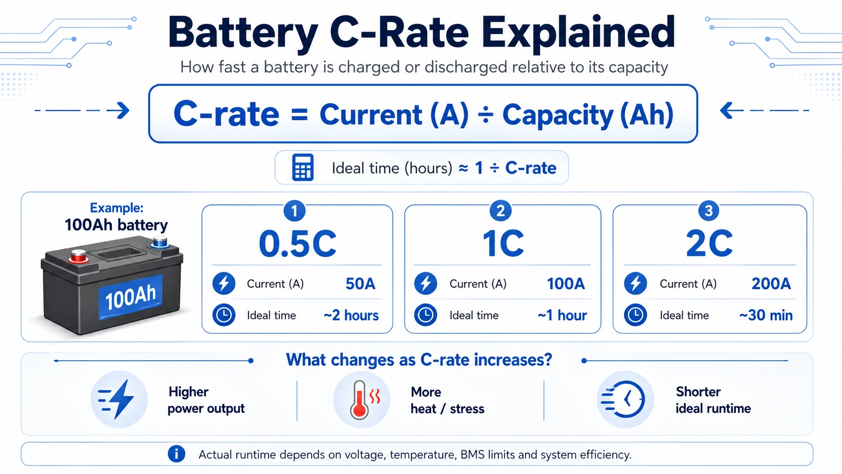
A battery’s C-rate shows how quickly it is being charged or discharged relative to its rated capacity. A 1C rate means the current equals the battery’s Ah capacity, while 0.5C means half that current and 2C means twice that current.
For example, discharging a 100Ah battery at 100A equals 1C. Discharging it at 50A equals 0.5C, while drawing 200A equals 2C.
The basic formula is: C-rate = Current (A) ÷ Battery Capacity (Ah)
C-rate helps engineers, installers and battery buyers compare current stress across batteries of different sizes.
This guide explains the battery C-rate formula, compares common C-ratings and shows how to apply C-rate when selecting LiFePO4 batteries, inverters and energy storage systems.
What Is C Rate in a Battery?
C-rate is a normalized measurement that compares battery current with rated amp-hour capacity. It tells you how quickly the battery is being asked to store or release charge, allowing a 5Ah cell, 100Ah battery and 314Ah energy-storage module to be evaluated using the same relative scale.
A 1C discharge current is numerically equal to the battery capacity in amp-hours:
- 5Ah battery at 1C = 5A
- 100Ah battery at 1C = 100A
- 280Ah battery at 1C = 280A
- 314Ah battery at 1C = 314A
The technical unit of C-rate is inverse hours, or h⁻¹, although battery datasheets normally write it simply as 0.5C, 1C or 2C.
What Do 0.2C, 0.5C, 1C and 2C Mean?
A C-rate number expresses current as a fraction or multiple of battery capacity. At 0.5C, current equals half the Ah rating; at 1C, it equals the full Ah rating; and at 2C, it equals twice the Ah rating. C/10 is another way of writing 0.1C.
Battery C-Rate Chart
| C-rate | Alternative Notation | Current From a 100Ah Battery | Theoretical Time |
|---|---|---|---|
| 0.05C | C/20 | 5A | 20 hours |
| 0.1C | C/10 | 10A | 10 hours |
| 0.2C | C/5 | 20A | 5 hours |
| 0.5C | C/2 | 50A | 2 hours |
| 1C | 1C | 100A | 1 hour |
| 2C | 2C | 200A | 30 minutes |
| 5C | 5C | 500A | 12 minutes |
The theoretical relationship is: Time in hours = 1 ÷ C-rate
This relationship is useful for quick comparisons, but it assumes the full rated capacity remains available at that current and that no voltage, temperature, SOC or BMS limit interrupts operation.

How Do You Calculate Battery C-Rate?
Calculate battery C-rate by dividing the actual charge or discharge current by the battery’s rated capacity in amp-hours. Use amperes with amp-hours, or milliamperes with milliamp-hours. The capacity and current units must match before the result can be interpreted correctly.
Formula 1: Calculate C-rate
C-rate = Current (A) ÷ Capacity (Ah)
Example:
- Battery capacity: 200Ah
- Discharge current: 80A
80A ÷ 200Ah = 0.4C
The battery is discharging at 0.4C.
Formula 2: Calculate Current
Current (A) = Capacity (Ah) × C-rate
Example:
- Battery capacity: 280Ah
- Required rate: 0.5C
280Ah × 0.5C = 140A
A 280Ah battery operating at 0.5C carries 140A.
Formula 3: Estimate Ideal Time
Ideal time (hours) = 1 ÷ C-rate
Example:
1 ÷ 0.25C = 4 hours
This calculation assumes constant current, full rated capacity and no cutoff, tapering, efficiency loss or derating. It should therefore be treated as an initial estimate rather than a guaranteed runtime.
For a more detailed explanation of battery-side current, see Avepower’s guide to battery discharge current.
Not Sure What C-Rate Your Battery System Needs?
Share your inverter power, battery voltage, required runtime and load profile. Avepower can help calculate the required charge and discharge current and recommend a suitable LiFePO₄ battery configuration.
What Is the Difference Between C-Rate, Ah, Amps, kW and kWh?
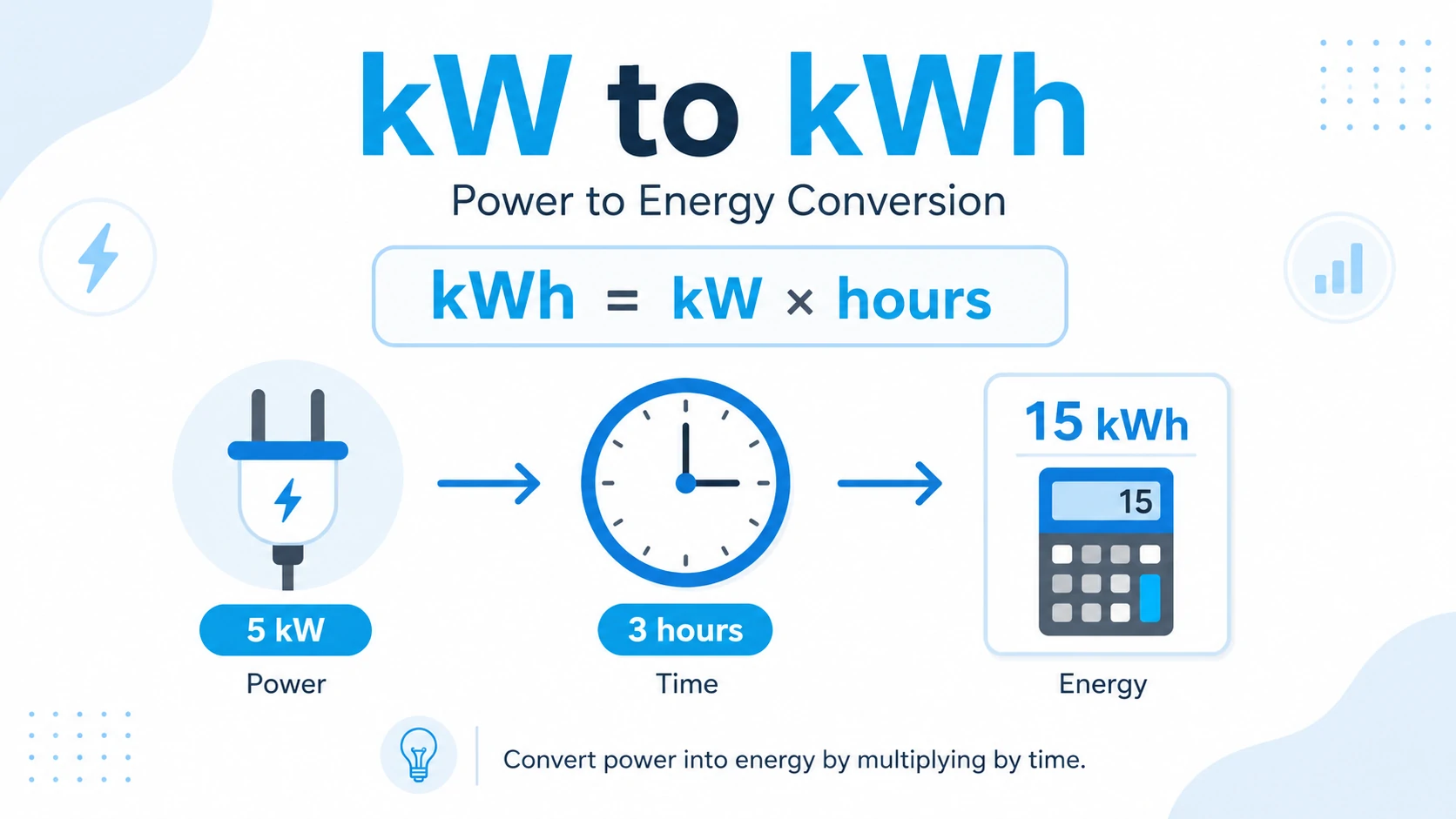
C-rate describes relative operating speed, while Ah describes charge capacity, amps describe actual current, kWh describes stored energy and kW describes instantaneous power. None of these values should be used alone when selecting a solar battery, inverter or commercial energy-storage system.
| Metric | What it Describes | Basic Relationship | Main Decision |
|---|---|---|---|
| Ah | Electrical charge capacity | Current × time | How much charge is stored |
| A | Actual current | Power ÷ voltage | Cable, BMS and protection load |
| C-rate | Current relative to Ah | A ÷ Ah | Relative charge or discharge stress |
| kWh | Stored energy | Voltage × Ah ÷ 1,000 | Potential backup duration |
| kW | Power delivered at one time | Voltage × current ÷ 1,000 | Load and inverter capability |
| SOC | Remaining charge percentage | BMS estimate | Current operating reserve |
| BMS current limit | Permitted pack current | Product-specific | Actual operating ceiling |
A 100Ah label does not automatically mean the battery can safely deliver 100A. It only reaches 1C at 100A. Whether 1C is permitted depends on the cells, busbars, terminals, BMS, enclosure, cooling and manufacturer specifications.
For additional context, Avepower’s guides explain what Ah means on a battery, battery capacity in Ah, Wh and kWh and the difference between energy capacity and battery power rating.
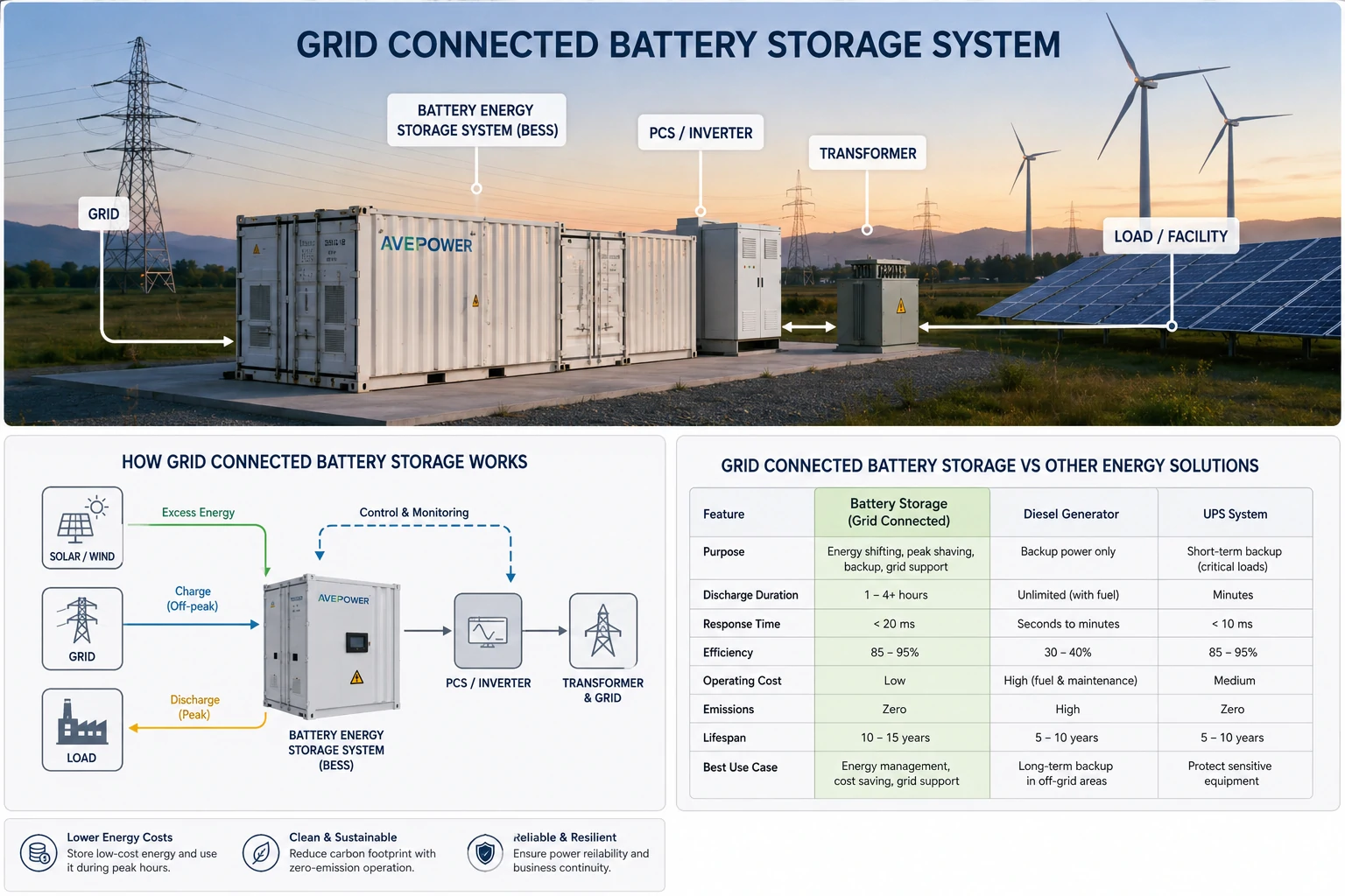
How Is C Rate Used in Battery Energy Storage Systems?
In larger battery energy storage systems, engineers often estimate system duration by dividing rated power in kilowatts by nominal energy in kilowatt-hours. A 50kW/100kWh system has a 0.5-per-hour power-to-energy ratio and can theoretically operate at rated power for about two hours before system losses and reserves.
The system-level shortcut is:
Approximate system rate = Rated power (kW) ÷ Nominal energy (kWh)
Example:
- Nominal battery energy: 100kWh
- Rated discharge power: 50kW
50kW ÷ 100kWh = 0.5h⁻¹
This is often described as a 0.5C or two-hour battery system.
However, kW/kWh is technically a power-to-energy ratio. The battery’s electrical C-rate should still be checked from pack current and Ah capacity because:
- Battery voltage changes during discharge.
- PCS efficiency is below 100%.
- Auxiliary loads consume energy.
- The BMS may reduce current at high or low temperature.
- Usable energy may be lower than nominal energy.
- Current increases as DC voltage falls for a constant-power load.
Need a Custom C-Rate for Your Energy Storage Product?
Avepower supports OEM and ODM battery systems with configurable capacity, current limits, BMS communication, enclosure design and parallel expansion for installers, distributors and energy brands.
Is Charge C-Rate the Same as Discharge C-Rate?
Charge C-rate and discharge C-rate use the same mathematical formula, but their permitted values are often different. A battery may safely discharge at a relatively high current while accepting a lower charging current, especially at low temperature, high SOC or near the end of a constant-voltage charging stage.
A datasheet may therefore list:
- Standard charge current
- Maximum charge current
- Recommended discharge current
- Maximum continuous discharge current
- Peak or pulse discharge current
- Charge and discharge temperature ranges
Suppose a 280Ah battery has:
- Maximum charge current: 100A
- Maximum continuous discharge current: 200A
Its corresponding rates are:
- Charge rate: 100A ÷ 280Ah = 0.36C
- Discharge rate: 200A ÷ 280Ah = 0.71C
This does not mean 0.36C charging and 0.71C discharging are always available. The BMS may reduce current when cell temperature, SOC, cell-voltage difference or communication status moves outside the preferred range.
Why Does Actual Runtime Differ from 1 ÷ C-Rate?
The expression 1 ÷ C-rate gives an ideal full-capacity time, not a guaranteed operating time. Real batteries reach voltage cut-off, temperature limits or BMS protection thresholds before every rated amp-hour is necessarily delivered, while chargers may reduce current during the final charging stage.
Actual charge or discharge time depends on:
- Usable rather than nominal capacity
- Initial and final SOC
- Depth of discharge
- Cell temperature
- Battery age and state of health
- Voltage sag under load
- Internal resistance
- BMS reserve and protection settings
- Charger or inverter efficiency
- Constant-voltage charging time
- Auxiliary loads such as fans, pumps or controls
For example, a 100Ah battery discharged at 1C theoretically supplies 100A for one hour. In practice, it may reach its lower voltage limit earlier if the cells are cold, aged or operating with high resistance.
How Does C Rate Affect Battery Power, Heat and Cycle Life?
Higher C-rate increases available power, but it also raises current-related losses, voltage drop and thermal demand. The result depends on cell chemistry, electrode design, internal resistance, cooling, temperature and SOC. A high C-rate can be appropriate when the battery is specifically designed and tested for high-power operation.
Power Output
At a given voltage:
Power = Voltage × Current
Because:
Current = Capacity × C-rate
The approximate nominal battery power is:
Power = Voltage × Capacity × C-rate
For a 51.2V, 100Ah battery:
| C-Rate | Current | Nominal DC Power |
|---|---|---|
| 0.2C | 20A | 1.024kW |
| 0.5C | 50A | 2.56kW |
| 1C | 100A | 5.12kW |
| 2C | 200A | 10.24kW |
The real power changes with battery voltage and system limits.
Heat Generation
For a simplified fixed-resistance model, resistive heat follows:
Heat loss ∝ Current² × Resistance
Doubling current can therefore create approximately four times the resistive heat when resistance remains unchanged. Real batteries are more complex because resistance and polarization also change with temperature, SOC, age and current.
Effective Energy
At higher current, voltage sag may cause the system to reach its low-voltage cutoff earlier. The battery can therefore deliver less usable energy than it would during a slower capacity test.
Aging
High-rate operation does not produce the same aging result in every battery. Charging at high C-rate, especially at low temperature or high SOC, can be particularly demanding. Discharge rate, average SOC, depth of discharge, rest periods and thermal conditions must be considered together.
How Do Series and Parallel Connections Affect C-Rate?
Connecting batteries in series increases system voltage while retaining the same amp-hour capacity, whereas connecting identical batteries in parallel increases total amp-hour capacity and current capability. The calculated bank C-rate changes only when the current is compared with the resulting bank capacity and operating limits.
Batteries in Series
Three identical 100Ah batteries in series remain a 100Ah bank.
If the series bank carries 50A:
50A ÷ 100Ah = 0.5C
Series connection increases voltage, but the same current passes through every battery.
Batteries in Parallel
Three identical 100Ah batteries in parallel create a theoretical 300Ah bank.
If total bank current is 150A and it divides equally:
150A ÷ 300Ah = 0.5C
Each battery ideally supplies 50A, also equal to 0.5C.
However, equal current sharing requires compatible batteries, similar SOC, correct busbar design, balanced conductor resistance, approved parallel communication and proper protection. A higher theoretical bank current does not override the BMS limit of each module.
What Is a Good C Rate for LiFePO4 Batteries?
There is no universal best C-rate for every LiFePO4 battery. The correct rate is the lowest current that still meets the required power, charging window and backup duration while remaining inside the cell, BMS, temperature and system limits stated in the approved datasheet.
The following ranges can be used only as early design references:
| Application Objective | Initial Design Range | Main Decision Factor |
|---|---|---|
| Long-duration solar self-consumption | 0.1C–0.3C | Energy duration and cycle life |
| Two-to-five-hour battery storage | 0.2C–0.5C | Daily power and thermal stability |
| One-to-two-hour peak shaving | 0.5C–1C | PCS power and cooling |
| Short backup or high-power loads | 1C or higher | Approved continuous rating |
| Motor startup or surge support | Peak rating | Maximum duration and recovery time |
These are not safety ratings. A specific LiFePO4 product may be designed below or above these ranges.
For stationary storage, choosing a lower daily operating rate can provide:
- Lower current through cables and terminals
- Less voltage sag
- Lower thermal stress
- More design margin at low SOC
- Greater tolerance for temperature derating
- Easier inverter and BMS coordination
A higher rate may be necessary when the project requires:
- High inverter output from limited capacity
- One-hour peak shaving
- UPS support
- Motor or compressor startup
- Fast charging during a short tariff window
- High-power commercial demand response
How Should You Read C Rate on a Battery Datasheet?
A reliable C-rate assessment requires more than dividing one current value by Ah capacity. Identify whether each value is recommended, continuous, maximum or pulse-rated, then confirm its temperature, duration, voltage, SOC and test conditions. The lowest applicable system limit determines the usable current.
Check these fields:
- Nominal capacity: Confirm whether capacity is rated at C/20, C/10, 0.5C, 1C or another test rate.
- Standard charge current: Usually the preferred charging reference.
- Maximum charge current: Check temperature and SOC restrictions.
- Recommended discharge current: Useful for normal daily operation.
- Maximum continuous current: The sustained upper limit.
- Peak current: Confirm the permitted number of seconds.
- Working voltage range: Required for inverter current calculations.
- Charge and discharge temperatures: Charging limits may differ from discharge limits.
- BMS current limit: Check whether it is continuous, delayed or instantaneous.
- Cycle-life conditions: Confirm C-rate, DOD, temperature and end-of-life capacity.
- Cell, module or pack rating: Do not apply a cell rating directly to a complete pack.
- Communication limits: A closed-loop BMS may change allowed current in real time.
The Avepower guide to battery communication explains how a BMS can send charge current limits, discharge current limits, temperature, SOC and alarm data to a compatible inverter.
How Do You Match Battery C Rate to an Inverter?
To match a battery with an inverter, calculate the inverter’s maximum battery-side DC current at the lowest expected operating voltage, convert that current into C-rate and compare it with the battery’s continuous discharge limit. Nominal-voltage calculations alone can underestimate current near the bottom of the discharge range.
Use this formula:
Required DC current ≈ AC output power ÷ Battery voltage ÷ Inverter efficiency
Then calculate:
Required battery C-rate = Required DC current ÷ Battery capacity
Example
Assume:
- Inverter output: 5,000W
- Battery voltage: 51.2V
- Inverter efficiency: 92%
- Battery capacity: 200Ah
Required current at nominal voltage:
5,000W ÷ 51.2V ÷ 0.92 = approximately 106A
Required C-rate:
106A ÷ 200Ah = approximately 0.53C
Now repeat the calculation at 44V:
5,000W ÷ 44V ÷ 0.92 = approximately 124A
124A ÷ 200Ah = approximately 0.62C
The battery should therefore support more than 124A continuously under the relevant temperature, SOC and installation conditions. Additional margin may be needed for surge loads, cable voltage drop and aging.
Use the Avepower inverter size chart for additional load calculations, and verify the exact model through the battery inverter compatibility list.
Example: What Is the C Rate of a 51.2V 314Ah Battery?
Avepower’s 51.2V 314Ah LiFePO4 battery provides a practical example of why standard, maximum and peak currents must be converted separately. Its listed current values correspond to 0.2C standard charging, 0.5C maximum charging, 0.5C continuous discharge and approximately 0.64C short-duration discharge.
The Avepower 51.2V 314Ah 16kWh LiFePO4 battery lists the following parameters:
| Parameter | Product Value | C-rate Calculation | Result |
|---|---|---|---|
| Nominal capacity | 314Ah | — | — |
| Nominal energy | 51.2V × 314Ah | — | 16.0768kWh |
| Standard charge current | 62.8A | 62.8 ÷ 314 | 0.20C |
| Maximum charge current | 157A | 157 ÷ 314 | 0.50C |
| Continuous discharge current | 157A | 157 ÷ 314 | 0.50C |
| Short-duration discharge | 200A for up to 300 seconds | 200 ÷ 314 | 0.64C |
| Nominal continuous DC power | 51.2V × 157A | — | 8.04kW |
| Nominal short-duration DC power | 51.2V × 200A | — | 10.24kW |
The product page also specifies CC-CV charging, a 40V–58.4V working range and temperature-dependent operating limits.
Illustrative 6kW Inverter Check
Assume a compatible 6kW inverter operates at 92% efficiency.
At 51.2V nominal voltage:
6,000W ÷ 51.2V ÷ 0.92 = approximately 127A
127A ÷ 314Ah = approximately 0.41C
This is below the listed 157A continuous discharge current.
At the 40V lower end of the working range:
6,000W ÷ 40V ÷ 0.92 = approximately 163A
163A ÷ 314Ah = approximately 0.52C
This exceeds the listed 157A continuous discharge current.
The example demonstrates why a battery that appears suitable at nominal voltage may need inverter derating, a higher low-voltage cutoff or an additional parallel battery at low SOC. Final settings must be confirmed using the exact inverter model, efficiency curve, surge requirement and Avepower-approved communication protocol.
Conclusion
Battery C-rate is the charge or discharge current divided by rated amp-hour capacity. It connects capacity, current, power and theoretical operating time, but it does not replace the battery datasheet. Safe selection still requires verification of continuous current, peak current, temperature, SOC, BMS limits and inverter compatibility.
Use C-rate to compare batteries and perform first-stage calculations, but make the final decision from complete system requirements rather than from a single advertised number.
For installers, distributors, EPC teams and OEM/ODM energy brands, Avepower can evaluate battery capacity, voltage platform, required C-rate, inverter power, communication protocol and expansion requirements. Submit the load profile, inverter model, required backup time and installation conditions through Avepower’s custom battery storage project service to receive a project-matched configuration. Avepower’s published product and project pages document support for customized capacity, cabinet layout, communication and high-voltage ESS integration.
Take Control of Your Energy with Avepower!
Reliable home solar battery solutions with OEM/ODM customization and in-house manufacturing, tailored to the needs of distributors, installers, and energy partners.
FAQ
A 1C rate means the current is numerically equal to the battery’s rated Ah capacity. A 100Ah battery operates at 1C when charging or discharging at 100A. The theoretical time is one hour, but actual time depends on usable capacity, voltage limits, temperature and system efficiency.
A 0.5C rate means the current equals half the battery’s Ah capacity. A 100Ah battery at 0.5C operates at 50A, while a 280Ah battery at 0.5C operates at 140A. The theoretical full-capacity time is two hours.
A 2C rate means the current equals twice the Ah capacity. A 20Ah battery operating at 2C supplies or receives 40A. The theoretical time is thirty minutes, but 2C operation is permitted only when the battery manufacturer approves it.
Only when the battery’s cells, BMS, terminals and complete assembly are approved for a continuous 1C discharge under the actual temperature and SOC conditions. A 100Ah capacity label alone does not confirm a 100A continuous current rating.
No. C-rate expresses charge or discharge current relative to capacity. Cold cranking amps, or CCA, measures a starting battery’s ability to deliver high current under a defined low-temperature test and is mainly associated with engine-starting batteries.