
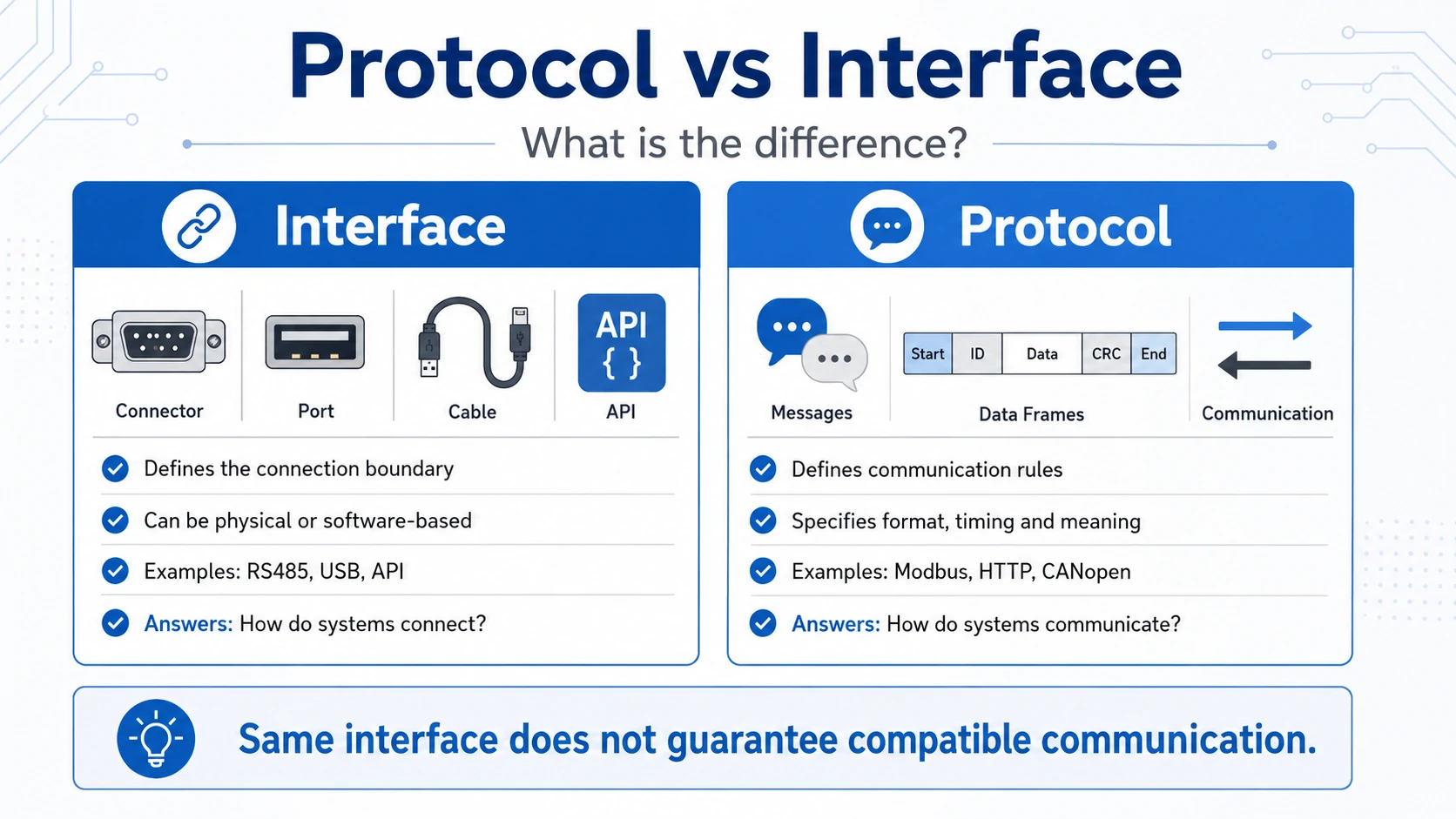
The difference between protocol and interface is that an interface defines the boundary or connection through which two components interact, while a protocol defines the rules, sequence and meaning of the information exchanged through that connection. Devices may use the same interface but still be incompatible when their protocols, settings or data definitions differ.
This distinction matters in computer networks, software APIs, industrial automation, embedded electronics and battery energy storage systems. Two products can have the same connector and electrical interface yet remain unable to communicate because their message formats, addresses, timing or protocol versions are different.
What Is the Difference Between Protocol and Interface?
An interface defines the accessible connection or boundary between systems, while a protocol defines the agreed behavior used across that boundary. The interface makes interaction possible; the protocol makes the interaction understandable. Compatibility normally requires both to match, together with configuration, data definitions and operating logic.
| Comparison Point | Interface | Protocol |
|---|---|---|
| Main purpose | Provides a connection or interaction boundary | Defines communication behavior and meaning |
| Main question | Where and through what mechanism do systems interact? | How and according to what rules do they communicate? |
| Can be physical? | Yes | May use physical-layer rules but is not limited to hardware |
| Can be logical or software-based? | Yes | Yes |
| Typical elements | Connector, pins, signals, API calls, functions, service boundary | Message format, addressing, timing, commands, responses, error handling |
| Examples | RS485 electrical interface, network interface, USB port, API | Modbus RTU, HTTP, TCP, CANopen, proprietary BMS protocol |
| Does matching it guarantee compatibility? | No | Not by itself |
| Typical failure | Wrong wiring, signal level or connector | Wrong message map, version, address or command sequence |
A useful way to remember the difference is:
Interface = the available path and boundary. Protocol = the rules and meaning used on that path.
However, this is a conceptual test rather than a universal naming rule. Some technology names cover both interface and protocol layers, so the actual specification must always be checked.
What Does an Interface Define?
An interface defines what one component exposes to another and how that interaction can physically or logically occur. Depending on the system, it may specify electrical signals, connector pins, callable functions, input and output parameters, service primitives or the boundary between two software or network layers.
Hardware and Electrical Interfaces
A hardware communication interface may define:
- Signal voltage and current characteristics
- Differential or single-ended signaling
- Connector and pin assignment
- Transmitter and receiver characteristics
- Duplex mode
- Bus topology
- Cable impedance
- Termination requirements
- Maximum loading conditions
What Does a Protocol Define?
A protocol defines the syntax, semantics, timing and behavioral rules followed by communicating entities. It can specify message fields, addresses, command codes, permitted sequences, acknowledgements, retries, error responses, timeouts and state transitions so that independently developed systems interpret the same exchange consistently.
A complete communication protocol may define:
| Protocol Element | Practical Meaning |
|---|---|
| Message syntax | The order, length and encoding of fields |
| Semantics | What each field or value means |
| Addressing | How senders, receivers or resources are identified |
| Device roles | Client/server, master/slave or peer-to-peer behavior |
| Timing | Response deadlines, frame gaps and retry intervals |
| Commands | Supported read, write, control or diagnostic operations |
| Error checking | CRC, checksum, acknowledgement or error codes |
| State behavior | What messages are valid in each operating state |
| Data model | Registers, objects, parameters or message identifiers |
| Failure behavior | Timeout, fallback, shutdown or reconnection logic |
How Do Protocols and Interfaces Work Together?
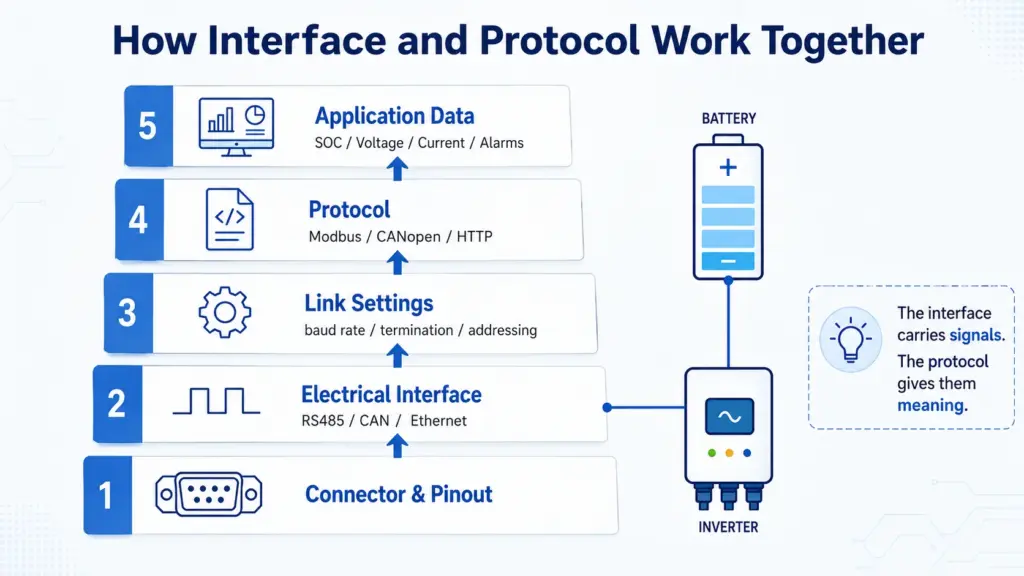
Protocols and interfaces normally operate as complementary layers. The interface provides an electrical, physical or software access mechanism, while the protocol uses that mechanism to exchange meaningful commands and data. Successful communication therefore requires a compatible path, compatible rules and matching implementation settings at every relevant layer.
Consider a typical industrial communication stack:
| Layer | Example Requirement |
|---|---|
| Connector | RJ45, DB9, terminal block or custom connector |
| Pinout | A/B, CAN-H/CAN-L, ground and shielding positions |
| Electrical interface | RS485, RS232, CAN transceiver or Ethernet PHY |
| Data-link behavior | Frame arbitration, addressing or serial framing |
| Transport | TCP, UDP or direct serial exchange |
| Application protocol | Modbus, CANopen, HTTP, IEC 61850 or proprietary BMS mapping |
| Data model | Registers, message IDs, scaling factors and alarm definitions |
| Operating logic | Charge permission, timeout response, derating or shutdown |
A communication failure can occur at any row.
For example, an RS485 cable may be correctly installed, but communication can still fail because:
- One device uses Modbus RTU and the other uses a proprietary format.
- The baud rates differ.
- The parity settings differ.
- Both devices are configured as clients or masters.
- Device addresses do not match.
- Register maps use different addresses.
- One system uses big-endian values and the other expects a different byte order.
- A value uses a 0.1 scaling factor on one side but a 1.0 factor on the other.
The presence of data on the wire only proves signal transmission. It does not prove correct interpretation.
Are RS485, CAN, Ethernet and Modbus Interfaces or Protocols?
RS485 is primarily an electrical interface, Modbus is primarily an application protocol, and CAN defines important lower-layer communication behavior while supporting multiple higher-layer protocols. Ethernet and USB are broader technology families that define several layers, so their classification depends on the technical context.
| Technology | Best Practical Classification | What It Mainly Defines | Important Limitation |
|---|---|---|---|
| RS232 | Electrical serial interface | Voltage levels and point-to-point signaling | Does not define application data meaning |
| RS485 | Electrical serial interface | Differential drivers and receivers | Does not define a protocol |
| UART | Hardware/peripheral and framing method | Start bits, data bits, parity and stop bits | Usually needs a separate application protocol |
| Modbus RTU | Application protocol with serial framing | Function codes, addresses and data objects | Register maps can still be vendor-specific |
| Modbus TCP | Modbus application protocol over TCP/IP | Modbus messages transported on IP networks | Device data definitions must still match |
| CAN | Physical and data-link technology | Arbitration, frames and error handling | Higher-layer message meanings may be proprietary |
| CANopen | Higher-layer CAN protocol | Device profiles and application objects | Both devices must support relevant profiles |
| J1939 | Higher-layer CAN protocol | Parameter groups and network behavior | Designed around particular vehicle applications |
| Ethernet | Physical and data-link technology family | Frames, media access and physical variants | Does not define the application itself |
| TCP | Transport protocol | Reliable ordered byte delivery | Does not define application data meaning |
| IP | Network-layer protocol | Addressing and packet routing | Does not guarantee application compatibility |
| HTTP | Application protocol | Request, response and resource semantics | Requires a compatible application implementation |
| USB | Multi-layer interconnect standard | Connectors, signaling, enumeration and transfers | Same connector does not guarantee equal capability |
| Bluetooth | Full wireless protocol stack | Radio, link, services and profiles | Devices need compatible profiles and roles |
Is RS485 an Interface or a Protocol?
RS485 is primarily an electrical interface standard, not a complete application communication protocol. It defines balanced differential signaling and transmitter-receiver characteristics, but it does not define register meanings, device commands or application data. A higher-level protocol such as Modbus RTU is normally required to make the transferred data useful.
Is CAN an Interface or a Protocol?
CAN cannot always be classified as only an interface or only an application protocol. The term may refer to the physical bus, the CAN data-link protocol or a wider technology family. Higher-level protocols such as CANopen or manufacturer-specific BMS mappings can operate above the CAN lower layers.
CAN is more complex than RS485 because the commonly used name covers several layers.
Does the Same Interface Mean Two Devices Are Compatible?
No. A matching interface only establishes that the devices may be electrically or logically connectable. They must also match in connector wiring, signal settings, device roles, addressing, frame structure, protocol version, data mapping, timing and operational behavior before reliable interoperability can be assumed.
A proper compatibility review should distinguish three levels.
Level 1: Physical compatibility
Confirm:
- Connector type
- Pin definition
- Signal voltage
- Polarity
- Grounding
- Isolation
- Cable type
- Termination
- Topology
Level 2: Communication compatibility
Confirm:
- Baud rate or bit rate
- Data bits
- Parity
- Stop bits
- Device address
- Identifier format
- Client/server or master/slave roles
- Frame timing
- CRC or error-checking method
- Protocol name and version
Level 3: Functional compatibility
Confirm:
- Required data points
- Read and write permissions
- Units and scaling
- Signed or unsigned data types
- Byte order
- Alarm definitions
- Control limits
- Heartbeat timing
- Timeout behavior
- Safe fallback mode
- Firmware support
For battery applications, the Avepower battery communication guide explains that the interface, pin definition, communication speed, device role, message format and supported protocol version all need to match.
How Can Interface and Protocol Performance Be Calculated?
Communication performance depends on both interface settings and protocol overhead. The interface determines the available bit rate, while the protocol determines how many addressing, command, data and error-checking bits must be transmitted. Effective update time must also include frame gaps, equipment processing and response delays.
Consider a Modbus RTU client reading ten 16-bit holding registers through RS485.
Step 1: Calculate the Request Length
A typical request contains:
| Request Field | Bytes |
|---|---|
| Device address | 1 |
| Function code | 1 |
| Starting address | 2 |
| Register quantity | 2 |
| CRC | 2 |
| Total | 8 bytes |
Step 2: Calculate the Response Length
Ten registers contain 20 data bytes:
| Response Field | Bytes |
|---|---|
| Device address | 1 |
| Function code | 1 |
| Byte count | 1 |
| Register data | 20 |
| CRC | 2 |
| Total | 25 bytes |
The Modbus specification defines each register as two bytes in the response for function code 03.
Step 3: Calculate Transmission Time at 9,600 bps
Assume an 8N1 serial configuration:
- 1 start bit
- 8 data bits
- 1 stop bit
- 10 transmitted bits per byte
Total request and response data:
8 bytes + 25 bytes = 33 bytes
Total transmitted bits:
33 × 10 = 330 bits
Basic wire time:
330 ÷ 9,600 = 0.034375 seconds
34.38 milliseconds
Modbus RTU also requires at least 3.5 character times between frames. Two 3.5-character intervals add approximately:
7 characters × 10 bits ÷ 9,600
7.29 milliseconds
Estimated minimum request-response line time:
34.38 ms + 7.29 ms
≈41.67 milliseconds
This excludes device processing time, bus turnaround and software scheduling. The official serial-line specification requires a minimum 3.5-character silent interval between RTU frames and treats excessive silence within a frame as an incomplete message.
At 19,200 bps, the equivalent theoretical line time falls to approximately 20.83 milliseconds. However, doubling the interface bit rate does not necessarily double the application update rate when device processing, polling strategy or network congestion becomes the main limitation.
This calculation demonstrates the distinction:
- RS485 and serial settings determine transmission capacity.
- Modbus framing determines the number and meaning of transmitted bytes.
- The application determines how frequently the data must be updated.
How Should You Check Interface and Protocol Compatibility?
Compatibility should be verified from the bottom layer upward, beginning with electrical and connector requirements and ending with application behavior. Testing only whether a cable fits or whether frames appear on a bus is insufficient; the received values must also be correctly decoded and produce the intended control response.
Use the following eight-part review.
| Check | Required Information | Typical Failure |
|---|---|---|
| 1. Connector | Connector model and mechanical keying | Cable fits incorrectly or cannot be secured |
| 2. Pinout | Signal names and pin positions | Reversed A/B or CAN-H/CAN-L |
| 3. Electrical layer | RS485, RS232, CAN, Ethernet or other signaling | Incompatible voltage or transceiver |
| 4. Network settings | Bit rate, parity, addresses and termination | No frames or frequent errors |
| 5. Protocol | Protocol name, revision and device role | Frames are rejected |
| 6. Data mapping | Registers, IDs, units, scale and byte order | Values appear incorrect |
| 7. Timing | Polling rate, heartbeat, timeout and retry | Intermittent offline alarms |
| 8. Control logic | Permissions, limits and fallback behavior | Monitoring works but control fails |
A useful commissioning test should include more than reading SOC. It should verify at least:
- Pack voltage
- Charge and discharge current
- Temperature
- SOC and SOH
- Charge voltage limit
- Charge current limit
- Discharge current limit
- Charge and discharge permission
- Alarm status
- Heartbeat or communication status
The system should then be tested under changing operating conditions. For example, reducing the BMS charge current limit should cause a compatible inverter or PCS to reduce its requested charging power within the approved response time.
What Does a Real Energy Storage Project Show?
A real C&I energy storage specification should list communication interfaces separately from communication protocols. This prevents procurement teams from assuming that RS485, Ethernet or CAN alone determines interoperability and gives integrators a clearer basis for matching the battery, PCS, EMS and site-control platform.
Avepower’s Germany 215kWh liquid-cooled C&I energy storage project provides a clear example.
The project specification includes:
| Project Parameter | Value |
|---|---|
| Nominal energy | 215.04 kWh |
| Rated voltage | 768 V |
| Voltage range | 672–864 V |
| Rated power | 100 kW |
| Maximum output | 110 kW |
| Communication interfaces | RS485, Ethernet and CAN |
| Communication protocols | IEC 61850, Modbus RTU and Modbus TCP |
The page deliberately separates communication interface from communication protocol. RS485 and CAN describe available communication paths or lower-layer capabilities, while Modbus RTU, Modbus TCP and IEC 61850 define higher-level communication behavior.
This separation provides real decision value:
- The PCS supplier can confirm whether its preferred network path is available.
- The EMS integrator can confirm whether the required application protocol is supported.
- The commissioning team can request the correct register map or data model.
- The project developer can identify whether a gateway is required.
- The buyer can compare solutions without relying on an ambiguous “supports communication” statement.
Avepower’s 522.5kWh high-voltage ESS case also combines BMU and BCU architecture with CAN/RS485 communication and documented voltage-sampling capability, illustrating the role of communication in system-level monitoring and protection rather than only app-based data display.
How Should a Communication Specification Be Written?
A useful communication specification should identify every layer needed for integration rather than listing only a port name. At minimum, it should define the connector, pinout, electrical interface, network settings, protocol and version, data dictionary, timing, error behavior and supported control functions.
A recommended specification format is:
| Specification Field | Example |
|---|---|
| Connector | RJ45 |
| Pin definition | Pin 4 CAN-H, pin 5 CAN-L, pin 8 GND |
| Interface | High-speed CAN |
| Bit rate | 500 kbps |
| Topology | Linear bus |
| Termination | 120 ohms at both physical ends |
| Protocol | Manufacturer BMS protocol V2.3 |
| Identifier type | 29-bit extended |
| Device role | Battery transmits cyclic status and receives PCS commands |
| Data dictionary | Separate revision-controlled document |
| Update period | 100 ms |
| Heartbeat timeout | 1 second |
| Byte order | Big-endian |
| Scaling | Voltage 0.1 V/bit; current 0.1 A/bit |
| Failure response | PCS charge and discharge request reduced to zero |
| Firmware dependency | BMS firmware 3.8 or later |
For Modbus RTU, the equivalent document should identify the register map, read/write permissions, function codes, data types, scaling, byte order, invalid-value behavior and exception handling.
For battery procurement, Avepower’s battery communication guide and inverter compatibility list can be used together: the first explains the engineering layers, while the second helps buyers identify existing inverter profiles and request model-specific verification.
Build a Communication-Compatible Energy Storage System
A reliable energy storage project requires more than selecting batteries and inverters with matching port labels. The voltage platform, BMS logic, communication interface, protocol version, wiring, control limits and failure behavior should be reviewed as one integrated system.
Avepower supports residential and commercial LiFePO4 systems with CAN, RS485 and RS232 communication, inverter protocol matching and project-specific BMS integration. The 108kWh high-voltage battery system, for example, combines a 345.6V nominal platform with CAN/RS485 communication and high-voltage control for compatible PCS integration.
For distributors, installers, EPC teams and energy brands, Avepower also provides OEM/ODM battery customization covering capacity, cabinet design, communication configuration and BMS functions. Submit the inverter model, project power, required capacity and communication documents through the Avepower project contact page to request an engineering compatibility review before ordering.

Take Control of Your Energy with Avepower!
Reliable home solar battery solutions with OEM/ODM customization and in-house manufacturing, tailored to the needs of distributors, installers, and energy partners.
FAQ
No. An interface is the boundary or mechanism through which components interact, while a protocol defines the communication rules used during that interaction. Some standards include elements of both, but the concepts remain different.
RS485 is primarily an electrical signaling standard. It does not define application commands or data meanings. Modbus RTU, BACnet MS/TP and proprietary protocols are examples of protocols that may use an RS485 interface.
Modbus is a communication protocol family. Modbus RTU can operate over serial interfaces such as RS485, while Modbus TCP carries Modbus application messages through TCP/IP networks.
No. They must also use compatible wiring, baud rate, parity, device roles, addresses, message framing and application protocols. Two RS485 products may be completely incompatible at the data level.
An API defines the operations or resources a software component exposes. A protocol defines the rules used to exchange information. A remote API may use HTTP as its protocol, while a local API may not require a network protocol.
An interface is an interaction boundary, and a protocol defines communication behavior. A standard is a formally documented specification that may define an interface, a protocol or several layers together.
Provide the inverter or PCS brand, model, firmware, battery voltage range, required kWh and kW, communication method, protocol profile, module quantity, project application and available manuals or pinout diagrams.