
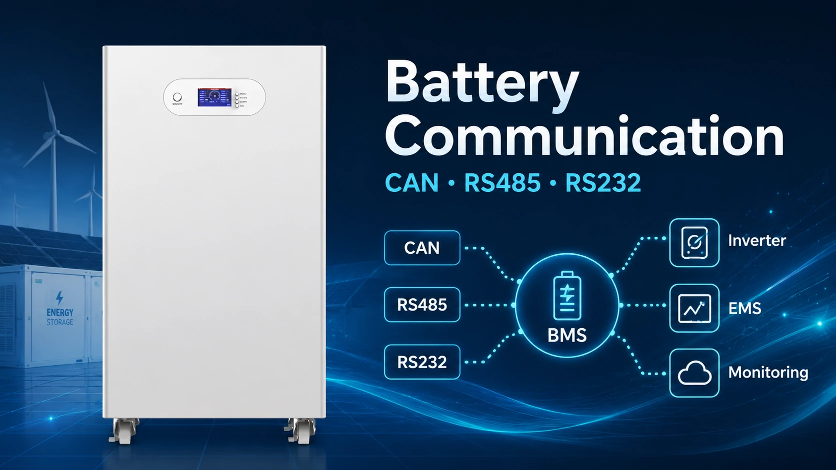
Battery communication is the exchange of operating data and control instructions between a battery management system, inverter, charger, energy management system and monitoring platform. In modern lithium battery systems, reliable communication helps control charging, limit discharging, report faults and maintain compatibility between components.
However, having the same connector or interface does not automatically make two devices compatible. A battery and inverter must normally match at several levels: electrical interface, pin definition, communication speed, device role, message format and supported protocol version.
This guide explains how battery communication works, how CAN differs from RS485 and Modbus, and how installers can prevent common BMS communication errors.
What Is Battery Communication?
Battery communication is the controlled exchange of voltage, current, temperature, state-of-charge, alarm and operating-limit data between a battery management system and external equipment. Its purpose is not merely to display information, but to help chargers, inverters and control systems operate the battery within approved electrical and thermal boundaries.
Inside a lithium battery, the BMS measures or calculates information such as:
- Cell and pack voltage
- Charge and discharge current
- Cell and pack temperature
- State of charge, or SOC
- State of health, or SOH
- Remaining capacity
- Cycle count
- Charge voltage limit
- Charge current limit
- Discharge current limit
- Warning and protection status
- Contactor or MOSFET status
The BMS then transfers selected data to an inverter, PCS, EMS, charger, display or service computer.
For example, when battery temperature rises or one cell approaches its upper voltage limit, the BMS may reduce the permitted charging current. A compatible inverter can read that limit and lower its output before the battery reaches a hard protection threshold. A modern battery monitoring system may therefore contain several communication layers rather than one single connection.
How Does Battery Communication Work?
Battery communication normally operates through several layers: an electrical interface carries the signal, a data-link method organizes transmission, and an application protocol defines what each message means. Successful integration requires compatibility at every layer; matching only the connector or port name is insufficient.
Not Sure If Your Battery and Inverter Can Communicate?
Send us your inverter model, battery voltage and required capacity. Avepower will help verify the communication protocol, interface and compatibility before installation.
What Information Does a Battery Send to an Inverter?
A communicating battery normally sends both status data and operating limits. Status data tells the inverter what is happening, while operating limits tell it what is currently permitted. For closed-loop control, charge voltage, charge current and discharge current limits are often more important than the SOC value alone.
A typical communication exchange may contain the following data.
| Data Category | Example Information | How the Inverter Uses it |
|---|---|---|
| Battery status | SOC, SOH, voltage, current | Displays battery condition |
| Temperature | Minimum, maximum or average temperature | Reduces charging in hot or cold conditions |
| Charge limits | Maximum charge voltage and current | Controls charger output |
| Discharge limits | Maximum permitted discharge current | Limits AC load output |
| Alarm data | Overvoltage, undervoltage, overtemperature | Stops or derates operation |
| System state | Charging, discharging, standby, fault | Selects operating mode |
| Identification | Battery model, protocol version, device address | Confirms system recognition |
What Is the Difference Between an Interface and a Protocol?
An interface describes how electrical signals travel, while a protocol describes how information is organized and interpreted. RS485, RS232 and CAN define important parts of the communication link, but successful integration also requires both devices to understand the same addresses, message identifiers, data fields and control logic.
This distinction prevents one of the most common battery communication mistakes.
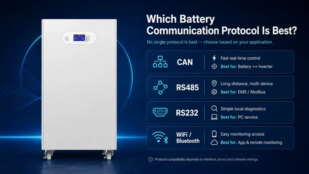
Which Battery Communication Protocol Is Best?
There is no universally best battery communication protocol. CAN is commonly selected for fast, deterministic control and robust error handling; RS485 is useful for multipoint serial networks and longer cable runs; RS232 suits local diagnostics; and WiFi or Bluetooth is normally used for monitoring rather than primary inverter control.
Battery Communication Protocol Comparison
| Protocol or Interface | Typical Topology | Relative Speed | Main Strengths | Main Limitations | Best Use |
|---|---|---|---|---|---|
| CAN / CAN bus | Multi-node bus | High | Arbitration, error detection, reliable real-time control | Protocol mapping and pinout remain manufacturer-specific | Battery-to-inverter, BMS-to-PCS |
| RS485 | Multipoint bus | Medium to high | Differential signaling, long-distance capability, strong noise resistance | RS485 alone does not define message meaning | Battery networks, EMS, Modbus RTU |
| RS232 | Point-to-point | Low to medium | Simple service connection | Shorter distance and one-to-one topology | PC diagnostics, firmware service |
| Modbus RTU | Application protocol, often over RS485 | Depends on serial settings | Structured registers and widely understood commands | Register maps are often vendor-specific | EMS, SCADA, industrial monitoring |
| UART | Point-to-point, board level | Application-dependent | Low cost and simple implementation | Limited noise immunity and distance | Internal BMS devices and displays |
| I²C / SPI | Short internal connection | Medium to high | Efficient communication between ICs | Not intended for long external cables | Sensors, memory and BMS controller boards |
| Bluetooth | Wireless, short range | Moderate | Easy local setup and smartphone access | Usually not used for safety-critical inverter control | Commissioning and local monitoring |
| WiFi / Ethernet | Networked monitoring | High | Remote dashboards and cloud access | Requires cybersecurity and network management | Remote monitoring, EMS and updates |
Verify Your Battery Communication Before Deployment
Avepower provides residential and commercial LiFePO4 battery systems with CAN, RS485 and RS232 communication options, along with inverter matching, protocol configuration and OEM/ODM engineering support.
Send Avepower your inverter brand, model, voltage range, required capacity and project application. The engineering team can review communication compatibility, recommend battery settings and prepare a project-specific integration solution.
When Should You Use CAN Battery Communication?
CAN is usually the stronger choice when the battery must exchange time-sensitive limits, status and fault information with an inverter, vehicle controller, BCU or PCS. Its message arbitration and error-management features make it suitable for electrically noisy, multi-node systems that require coordinated control.
CAN is commonly used for:
- Residential lithium batteries and hybrid inverters
- High-voltage battery clusters
- Electric vehicles and mobile equipment
- BMU-to-BCU communication
- Battery-to-PCS communication
- Parallel battery management
- Chargers requiring dynamic battery limits
Classical CAN commonly operates at up to 1 Mbit/s and carries up to eight data bytes per frame. CAN FD extends the available payload and permits a faster data phase, although both communicating devices must specifically support CAN FD before it can be used.
When Should You Use RS485 or Modbus?
RS485 is a practical choice for industrial monitoring, Modbus RTU, long cable routes and networks where a controller polls several devices. It is widely used between batteries, inverters, meters, PLCs, gateways and EMS equipment, but the complete protocol and register map must still match.
RS485 uses differential signaling, which helps reject electrical noise shared by both conductors. It can also support multiple devices on a bus when addressing and application-layer rules are correctly implemented.
What Is RS232 Used for in a Battery System?
RS232 is most useful as a local service, commissioning or diagnostic interface rather than the main communication bus for a large battery network. It commonly connects a BMS to a computer, display, firmware tool or USB-to-serial adapter so technicians can inspect parameters and logs.
Typical uses include:
- Reading detailed cell information
- Configuring protection thresholds
- Selecting an inverter protocol
- Exporting fault history
- Updating BMS firmware
- Testing charge and discharge MOSFET control
- Calibrating current or SOC
- Accessing manufacturer service software
RS232, RS485 and UART are not electrically interchangeable. Connecting a logic-level UART directly to an RS232 port can expose the controller to incompatible voltage levels. Use the manufacturer-specified cable or converter.
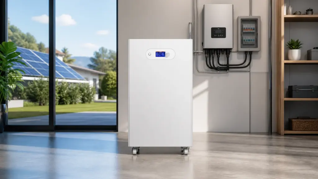
Avoid CAN and RS485 Compatibility Problems
Get technical support for protocol matching, cable pinout, BMS settings and inverter configuration for your residential or commercial energy storage project.
Are Bluetooth and WiFi Battery Communication Protocols?
Bluetooth and WiFi provide useful monitoring and maintenance connections, but they are normally separate from the wired communication controlling the inverter. A battery may continue operating with the inverter when its app connection is offline, provided the CAN or RS485 control link remains healthy.
Bluetooth may be used for:
- Local commissioning
- Viewing SOC and cell voltage
- Checking temperature and alarms
- Changing authorized BMS parameters
- Installer diagnostics
WiFi, Ethernet or a cellular gateway may support:
- Cloud dashboards
- Historical data
- Fleet monitoring
- Remote service
- Firmware updates
- SCADA or EMS integration
Wireless monitoring should not be presented as proof of inverter compatibility. A battery with Bluetooth but no compatible CAN or RS485 mapping may still be unable to exchange control data with a hybrid inverter.
Can a Lithium Battery Work Without BMS Communication?
Some lithium batteries can operate without communication when both manufacturers approve voltage-based control and all charging parameters are correctly configured. However, the inverter will not receive dynamic BMS limits or accurate internal status, so the local BMS becomes the final protection layer rather than part of coordinated closed-loop control.
This arrangement is often called open-loop or closed-loop operation.
Closed-loop Battery Communication
In a closed-loop system:
- The BMS calculates the current operating limits.
- The battery sends those limits to the inverter or PCS.
- The inverter adjusts charge or discharge output.
- The BMS continues monitoring the cells.
- Hard protection activates only when coordinated control is insufficient.
Closed-loop control is especially valuable when:
- Charging temperature changes significantly
- Multiple batteries are connected
- High charge or discharge power is required
- Accurate SOC is important
- The battery manufacturer requires communication
- Warranty terms specify approved inverter integration
Open-loop Operation
In an open-loop system, the installer enters fixed parameters such as:
- Bulk or absorption voltage
- Float voltage
- Low-voltage cutoff
- Maximum charge current
- Maximum discharge current
- Restart voltage
This may work for a supported off-grid configuration, but fixed settings cannot react as precisely to cell imbalance, low-temperature charging limits or temporary BMS derating.
Open-loop operation should not be used merely to bypass an unresolved communication error. It should be used only when the battery and inverter documentation permits it and the installer understands the required limits.
How Do Multiple Batteries Communicate in Parallel?
Parallel battery systems normally assign a unique address to each battery and select one primary unit to aggregate data for the inverter. Correct communication depends on the approved daisy-chain topology, device IDs, termination, current-sharing logic and the maximum number of batteries supported by both the BMS and inverter.
A typical low-voltage parallel system may operate as follows:
- Battery 1 is assigned as the primary battery.
- Batteries 2–N receive unique addresses.
- Inter-battery communication cables link the modules.
- The primary battery collects pack status and alarms.
- The primary battery sends aggregated information to the inverter.
- The inverter follows the total system limits reported by the battery group.
The addresses may be set through DIP switches, a display or configuration software. Some systems automatically assign addresses, while others require a defined sequence.
Parallel Battery Calculation Example
Assume four 51.2V, 100Ah battery modules are connected in parallel.
- Total capacity=100Ah×4=400Ah
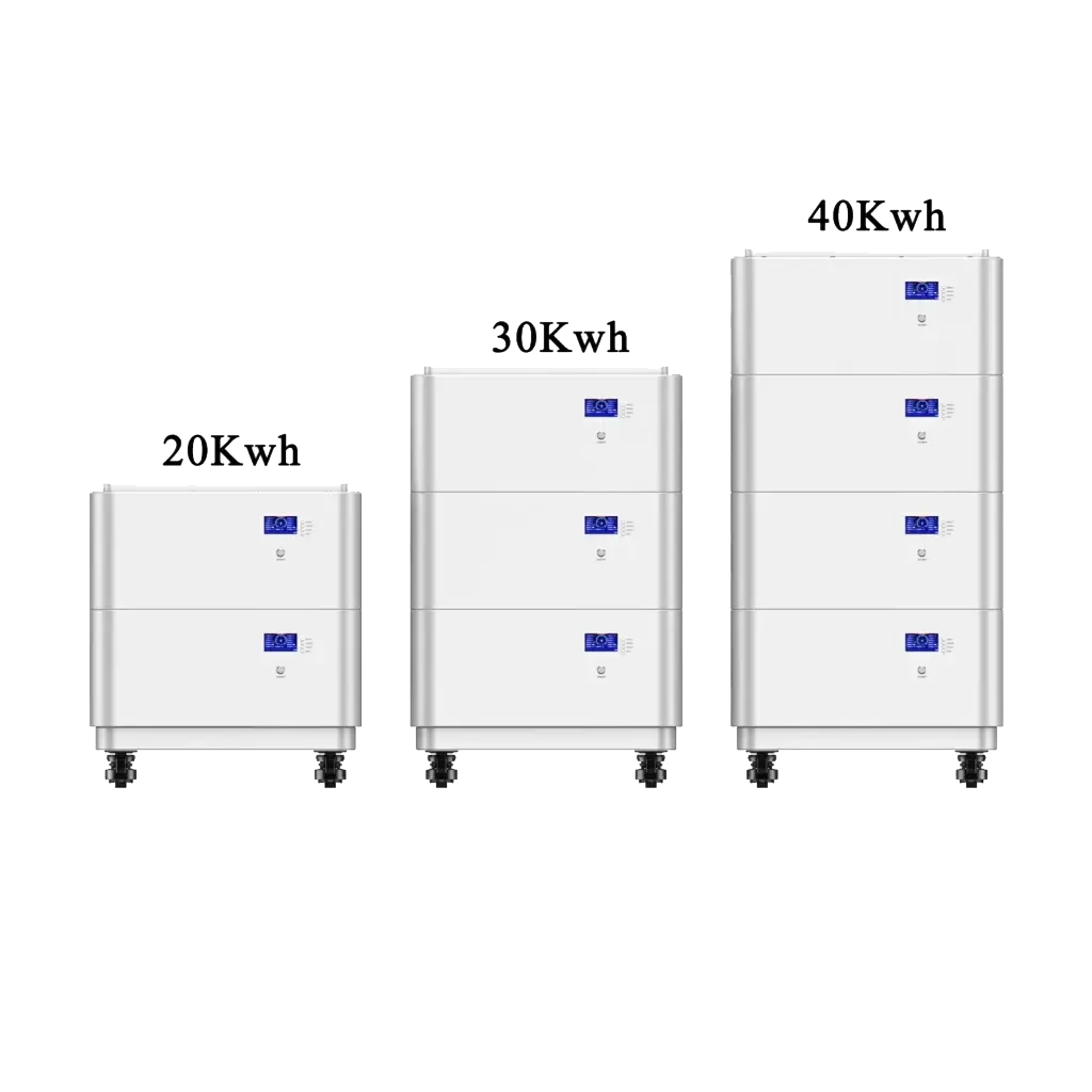
- Nominal energy=51.2V×400Ah=20,480Wh
- Nominal energy=20.48kWh
The voltage remains approximately 51.2V, while nominal amp-hour capacity increases to 400Ah.
However, the inverter should not assume that four modules automatically provide four times the permissible current. The final current limit must come from the approved BMS logic and manufacturer configuration. Cable size, fusing, busbars, temperature and module imbalance can all affect the usable current.
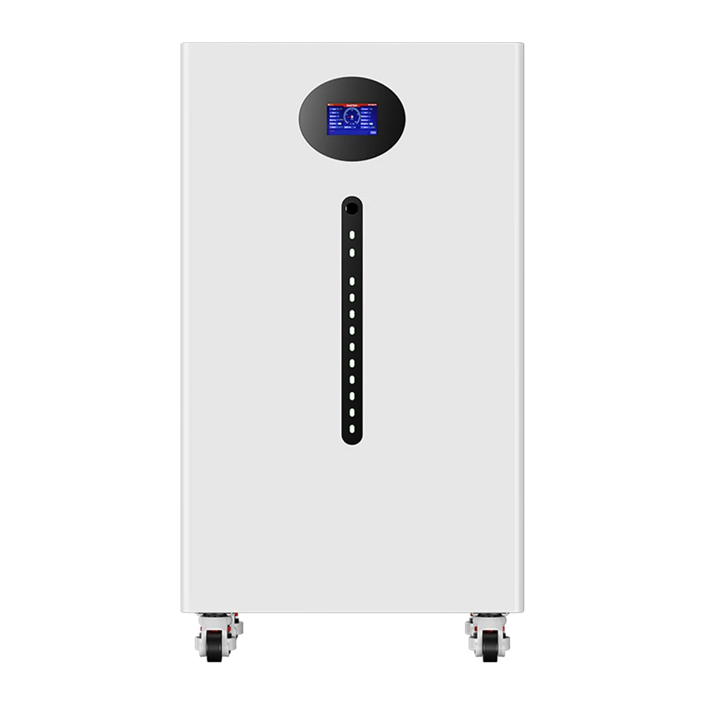
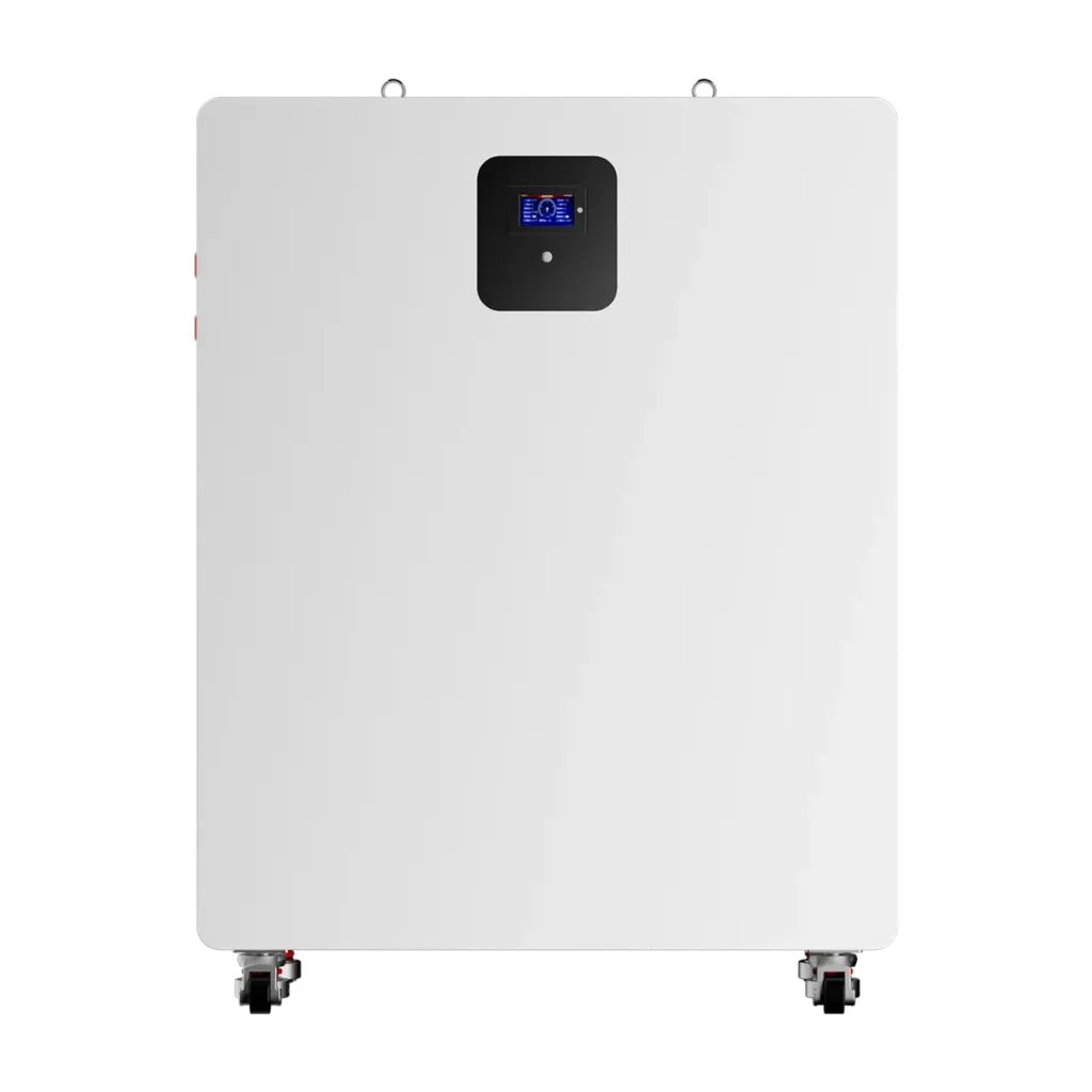
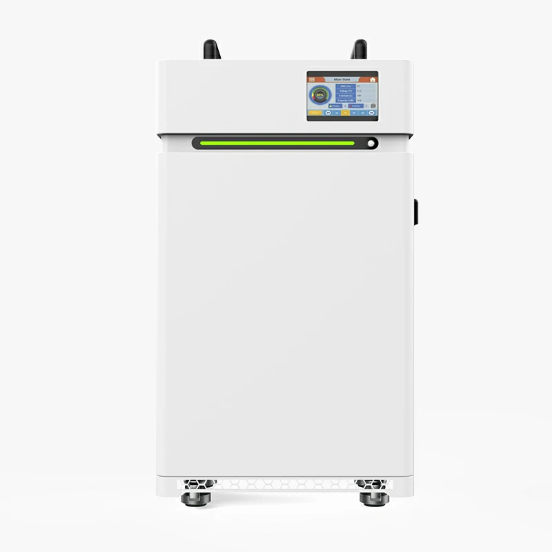
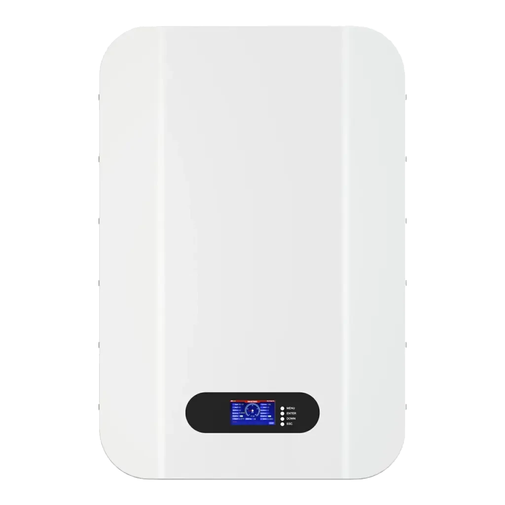
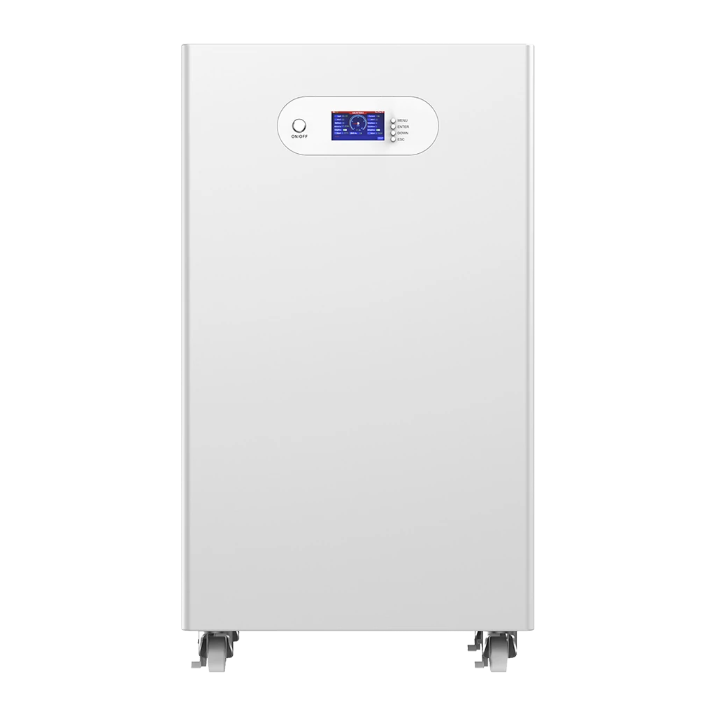
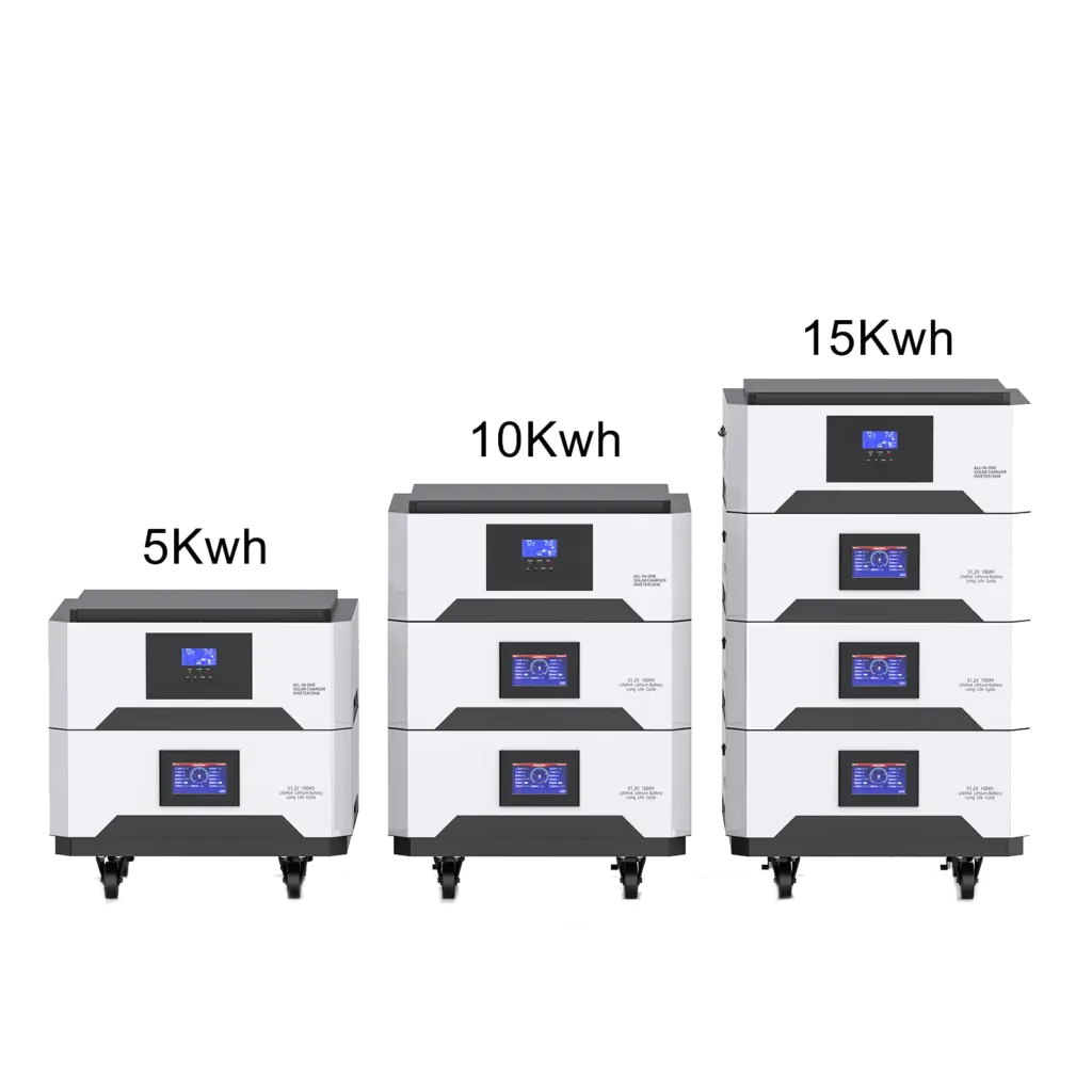
The Avepower 5kWh, 10kWh and 15kWh stackable battery system supports CAN, RS485 and RS232 communication, with published support for parallel expansion. Avepower specifically recommends confirming the inverter brand, model, communication protocol and parameter settings before ordering or installation.
How Should You Choose a Battery Communication Method?
Choose the communication method by starting with the inverter or host controller’s documented compatibility requirements, not by comparing interface speed alone. A technically capable interface has little value when the devices use different message maps, pin definitions or firmware versions.
Use the following decision guide:
| Application | Preferred Approach | Selection Priority |
|---|---|---|
| Single residential battery | CAN or supported RS485 protocol | Confirm exact inverter model and firmware |
| Parallel home batteries | CAN/RS485 with master-slave battery network | Verify addressing, master selection and maximum module count |
| Rack battery bank | CAN to inverter, RS485 between modules where specified | Follow the manufacturer’s port and DIP-switch sequence |
| High-voltage ESS | Isolated CAN or RS485 through BMU, BCU, PCS and EMS layers | Confirm isolation, topology, redundancy and timeout behavior |
| PLC or SCADA monitoring | Modbus RTU/TCP or documented gateway | Obtain a complete register map |
| PC diagnostics | RS232, USB-UART or service RS485 | Use the correct isolated converter and software |
| Mobile monitoring | Bluetooth LE | Restrict access to approved settings |
| Cloud fleet management | Ethernet, WiFi or cellular gateway | Apply authentication, logging and network segmentation |
For stationary storage, the right decision is usually the protocol already supported and validated by the inverter manufacturer.
How Can You Check Battery and Inverter Compatibility?
Battery-inverter compatibility must be confirmed at the model, firmware and protocol level. Brand-level statements are useful for initial screening, but they do not guarantee that every inverter series, voltage platform or software release will work with every battery.
Check all of the following before purchase or installation:
1. Voltage Platform
Confirm whether the system is:
- 12V or 24V low voltage
- 48V or 51.2V low voltage
- High voltage with series-connected modules
A low-voltage CAN protocol cannot make a high-voltage battery electrically compatible with a low-voltage inverter.
2. Inverter Model and Firmware
Record the complete model number and firmware version. One inverter family may use different protocols across regional or hardware variants.
3. Battery BMS and Firmware
Identify the BMS manufacturer, firmware version and available protocol profiles.
4. Communication Interface
Confirm whether the required link is CAN, RS485 or another interface.
5. Application Protocol
Verify the named protocol and version rather than accepting “CAN compatible” as sufficient.
6. Pin Definition
Check every RJ45 or terminal pin. CAN-H, CAN-L, RS485-A, RS485-B, ground and wake-up pins may differ between manufacturers.
7. Communication Settings
Verify:
- CAN bit rate
- RS485 baud rate
- Parity
- Device address
- DIP-switch position
- Master and slave roles
- Termination requirements
8. Required Data Objects
Ensure the inverter receives the charge and discharge limits, SOC, alarms and status values it needs.
Avepower publishes an inverter compatibility list showing supported protocol names and communication methods for brands such as Deye, GoodWe, Growatt, SMA, Solis and Victron. Because models and firmware can differ, Avepower also recommends an engineering compatibility check using the exact inverter model.
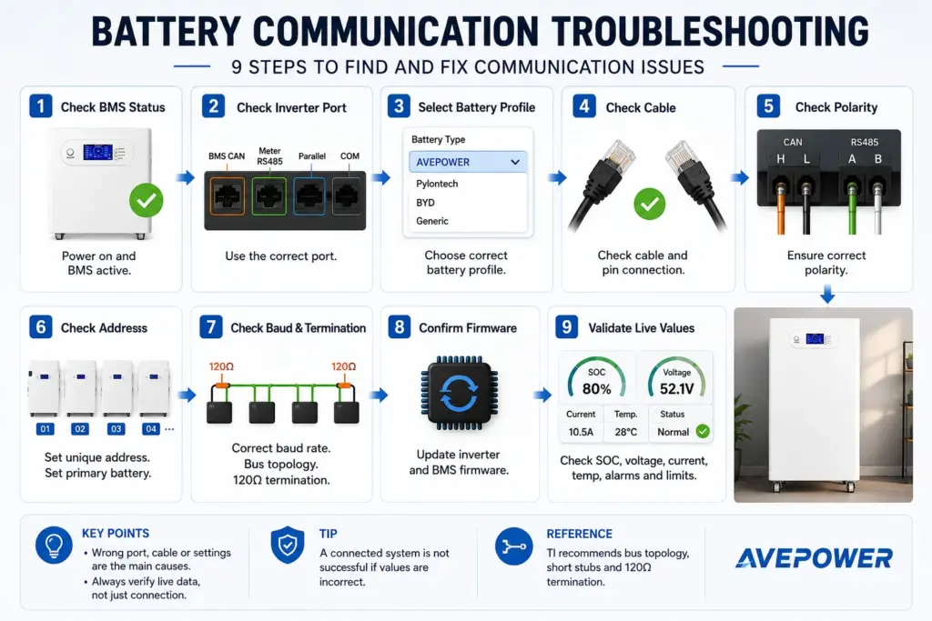
Why Is My Battery Not Communicating With the Inverter?
Most battery communication failures are caused by a mismatch in wiring, selected protocol, communication speed, address or firmware rather than a defective battery. Troubleshooting should start at the physical layer and proceed upward through network settings, application protocol and live data interpretation.
| Symptom | Likely Cause | Recommended Check |
|---|---|---|
| No BMS icon or immediate communication error | Wrong port, cable or pinout | Verify CAN/RS485 port labels and connector diagram |
| Battery detected but SOC is missing | Incomplete or wrong protocol mapping | Confirm the exact protocol profile |
| SOC or voltage is unrealistic | Scaling, byte order or register mismatch | Compare raw frames with the protocol document |
| Communication works with one battery but not several | Duplicate IDs or incorrect master selection | Check DIP switches and module sequence |
| Intermittent errors under high load | Noise, grounding, termination or routing problem | Inspect shielding and separation from power cables |
| Works at short distance but fails after cable extension | Signal integrity or topology problem | Check data rate, termination and cable specification |
| Inverter shows battery offline after a few seconds | Heartbeat or timeout mismatch | Confirm update interval and required periodic messages |
| Charge current remains very low | BMS is reporting a dynamic limit | Check temperature, SOC, cell voltage and alarms |
| App works but inverter does not | Bluetooth/WiFi is separate from CAN/RS485 | Configure the wired control connection |
| Data is visible but control is incorrect | Read-only integration or missing command objects | Confirm closed-loop functions, not only monitoring |
| RS485 link has multiple unstable devices | Star wiring, missing bias or termination | Rebuild according to the specified bus topology |
| Communication stopped after an update | Firmware or protocol-version change | Check release notes and restore a validated combination |
Practical Diagnostic Order
- Confirm pack voltage and BMS power.
- Check that the correct communication port is used.
- Verify the cable with a continuity tester.
- Confirm pin assignments.
- Check termination where required.
- Confirm battery addresses and master role.
- Select the correct inverter protocol.
- Verify baud rate or CAN bit rate.
- Review firmware compatibility.
- Capture communication frames if the error remains.
A CAN analyzer or isolated RS485-to-USB converter can help engineers determine whether the battery is transmitting, whether the inverter is requesting data and whether valid responses are being received.
Battery Communication Case Study: 522.496kWh High-Voltage ESS
Large high-voltage systems demonstrate why communication architecture must scale with battery architecture. In Avepower’s Lithuania project, BMUs, BCUs and upper-level equipment were coordinated through CAN and RS485 across two battery clusters, rather than treating the entire installation as one simple battery-to-inverter cable.
The project used:
- 522.496kWh total nominal energy
- 832V nominal DC voltage
- 628Ah nominal capacity
- Four 42U cabinets
- Two battery clusters
- Thirteen battery packs per cluster
- 20.096kWh per battery pack
- CAN and RS485 communication
- BMU and BCU management
- ±0.2% full-scale voltage-sampling accuracy
- 200A continuous system current
The capacity calculation is:
20.096kWh per pack × 13 packs per cluster × 2 clusters = 522.496kWh
This calculation confirms the energy architecture, but reliable operation also depends on the control architecture. Each BMU collects pack-level measurements, the BCU coordinates cluster-level data and protection, and the upper-level controller receives the information needed for system integration.
Avepower’s published 522.5kWh high-voltage ESS case study documents the two-cluster design, CAN/RS485 communication, BMS protection and cabinet configuration.
For larger projects, Avepower’s custom high-voltage battery storage systems support configurable voltage, capacity, cabinet layout, BMU/BCU logic, CAN or isolated RS485 communication and inverter matching. Its published BMU design supports cell-voltage measurement, temperature sampling, balancing, isolated CAN communication and cascading to the BCU.
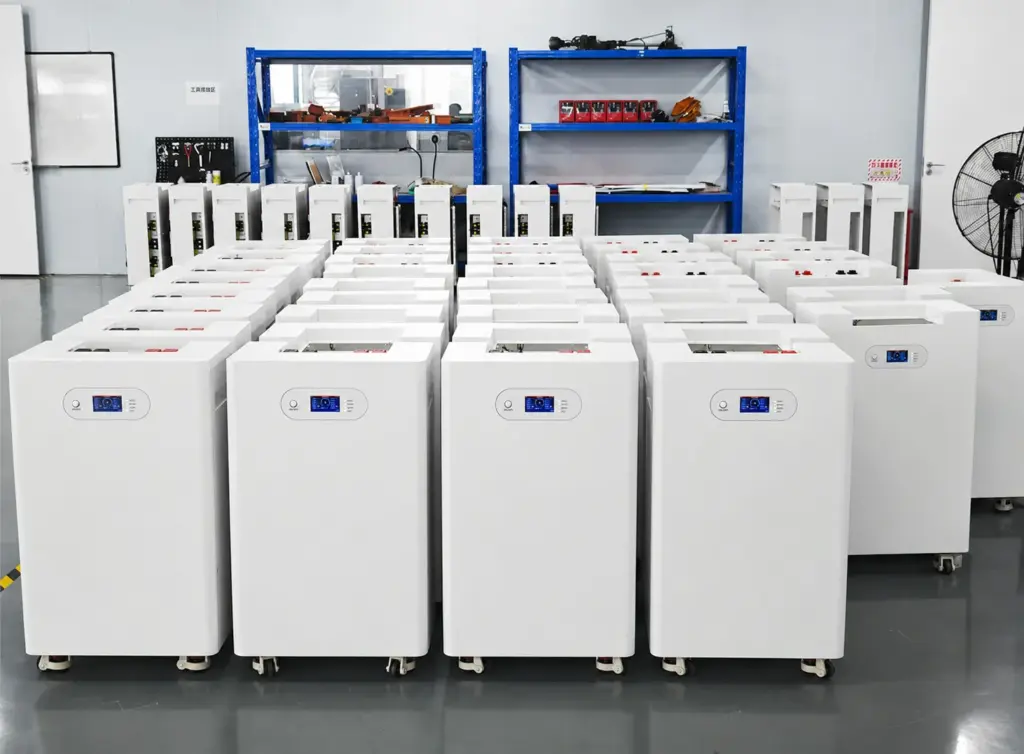
Build a Battery System That Communicates Reliably
Avepower provides LiFePO4 battery systems with CAN, RS485 and RS232 communication, inverter matching and OEM/ODM protocol customization.
How Does Battery Communication Affect Product Selection?
Communication capability should be evaluated as part of the battery system rather than as an optional feature. Buyers should ask whether the required inverter profile is already validated, whether protocol customization is available and whether engineering documentation will be supplied before shipment.
A technically useful battery specification should state:
- Supported interfaces
- Supported inverter protocols
- BMS manufacturer
- Firmware version
- Connector and pin definitions
- Maximum parallel quantity
- Addressing method
- Master-slave architecture
- Monitoring options
- Update and customization policy
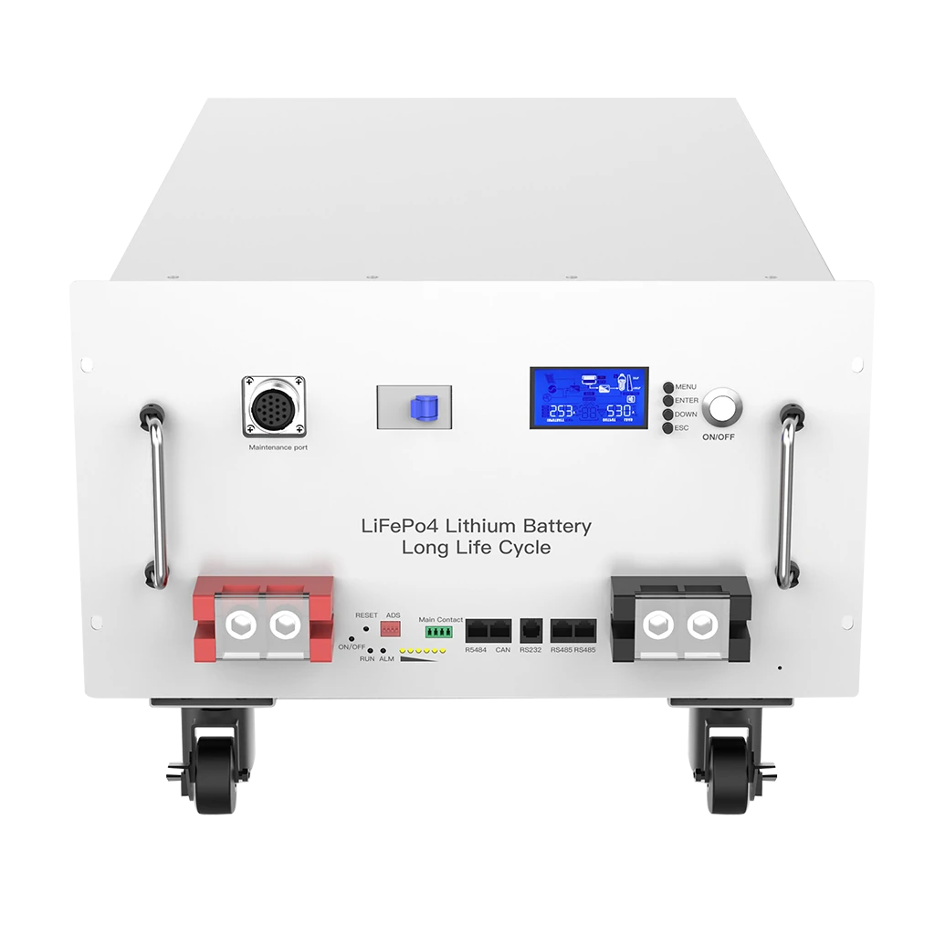
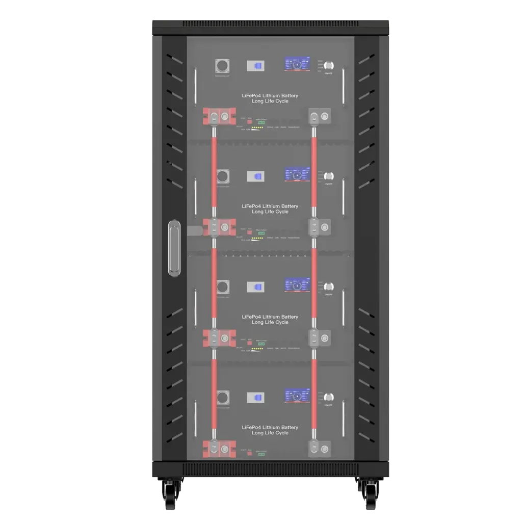
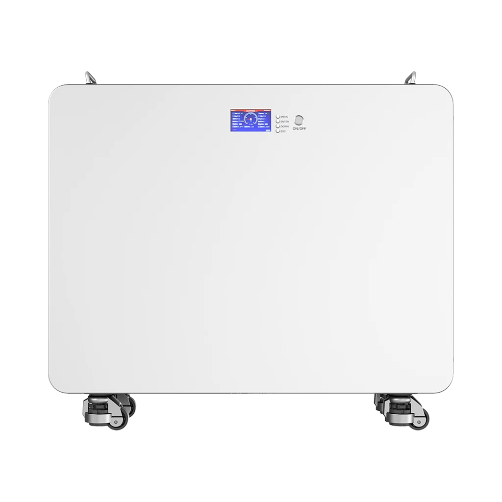
For example, the Avepower 48V 280Ah rack-mount battery supports CAN, RS485 and RS232 communication, a 200A maximum continuous discharge rating and up to 16 units in parallel. The page also identifies communication matching as an engineering requirement rather than assuming every inverter will work automatically.
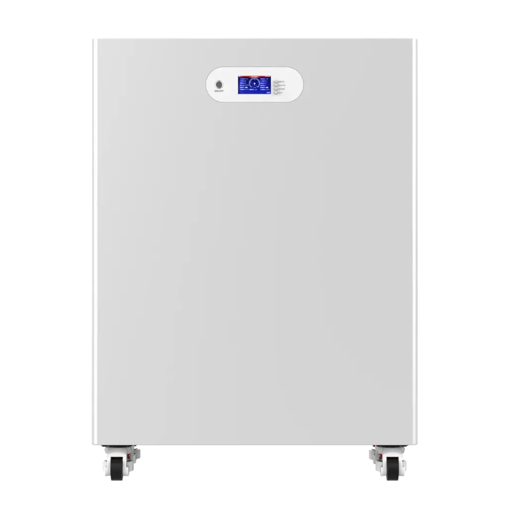
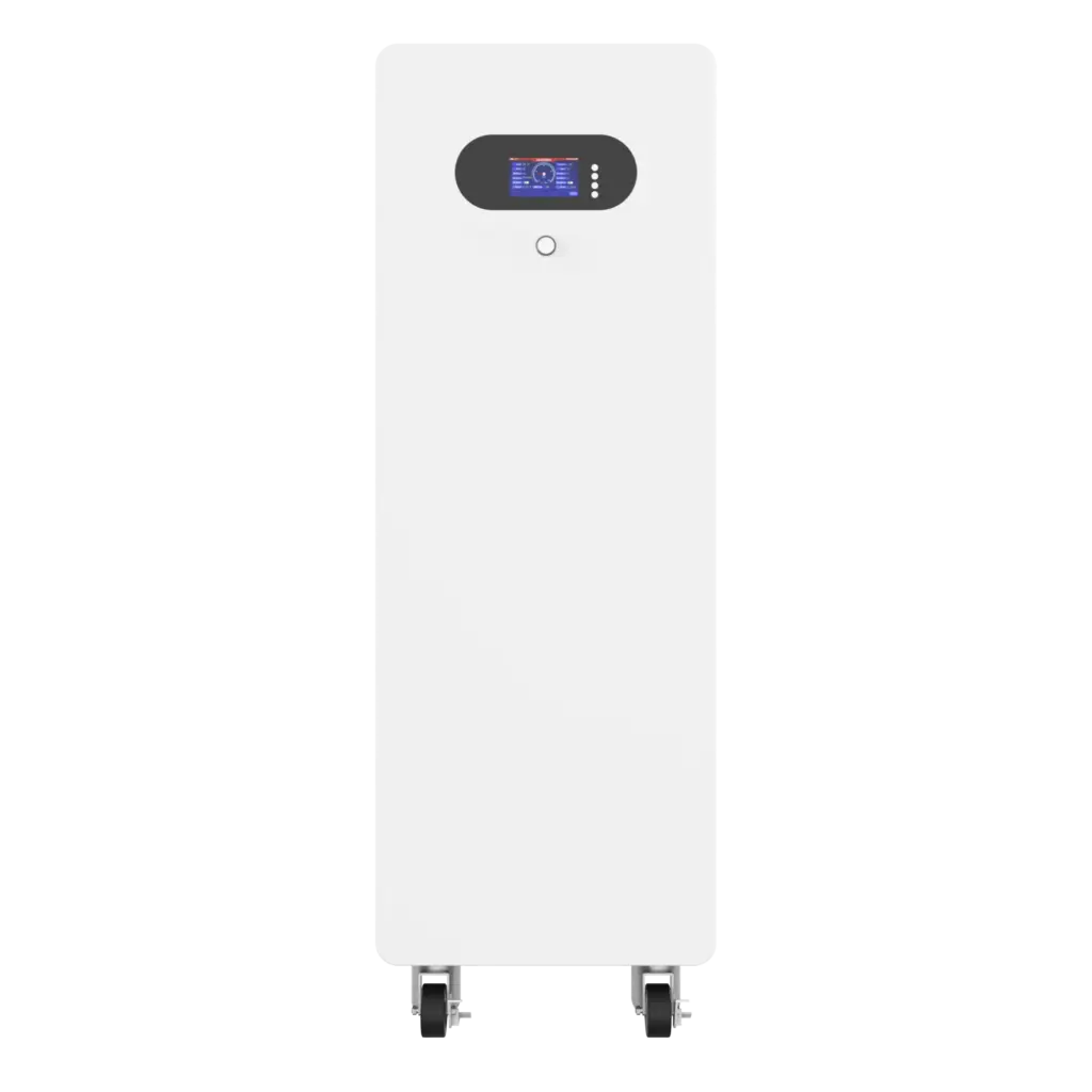
The Avepower 50kWh solar battery combines CAN, RS485 and RS232 with Bluetooth/WiFi monitoring, a 300A BMS and 2A active balancing. This illustrates the difference between wired inverter communication and wireless user monitoring within the same battery product.
For OEM and distributor projects, Avepower’s custom battery engineering service can adjust BMS protection logic, communication protocol, inverter matching, output ports, enclosure and documentation around the intended market and application.
How Should Battery Communication Be Secured?
Remote battery monitoring should be treated as an operational-technology connection rather than an ordinary consumer app. Systems connected to Ethernet, WiFi, cellular networks or cloud platforms require controlled access, documented assets, secure update procedures, logging and separation from untrusted networks.
Recommended measures include:
- Inventory all communication interfaces
- Disable unused radios and service ports
- Change default credentials
- Use role-based access
- Restrict parameter-writing permissions
- Separate BESS networks from office and guest networks
- Log configuration changes and remote sessions
- Validate firmware sources and digital signatures
- Maintain backups of known-good settings
- Apply secure update and rollback procedures
- Use encrypted remote connections
- Review gateway and cloud data-retention policies
Build an Inverter-Compatible Battery System With Avepower
Reliable battery communication starts before installation. The inverter model, voltage platform, protocol version, BMS logic, cable pinout, module quantity and monitoring requirements should all be confirmed during system design.
Avepower supports CAN, RS485 and RS232 integration across residential batteries, rack systems, vertical LiFePO4 batteries and high-voltage ESS projects. For installers, distributors, EPCs and OEM brands, the engineering team can help evaluate inverter compatibility, configure BMS protocols and develop project-specific communication solutions.
Contact Avepower for a battery communication and inverter compatibility review before finalizing your battery or energy storage system.
Take Control of Your Energy with Avepower!
Reliable home solar battery solutions with OEM/ODM customization and in-house manufacturing, tailored to the needs of distributors, installers, and energy partners.
FAQ
A complete battery communication specification should define the physical connection, network settings, data dictionary, timing, error behavior and supported operating functions. A list containing only “CAN/RS485” is insufficient for system integration or procurement.
A battery communication protocol defines how the BMS and other equipment format, transmit, receive and interpret battery data. It may specify addresses, message identifiers, register maps, scaling, alarms, control limits and timeout behavior.
No. RS485 mainly defines an electrical signaling interface. Modbus is an application-level messaging protocol that can operate over RS485, RS232, Ethernet or other supported transport methods.
CAN is often better for fast, event-driven control and fault reporting, while RS485 is often practical for industrial polling, Modbus integration and longer cable routes. Compatibility with the inverter is more important than selecting one based only on theoretical performance.
No. Both devices must use compatible pin assignments, bit rates, message identifiers, data formats and control logic. Sharing the CAN physical layer does not guarantee application-level compatibility.
Some batteries and inverters support voltage-based operation, but it must be explicitly permitted and correctly configured. The inverter will not receive the same dynamic limits, internal temperatures, detailed alarms or calculated SOC information available through closed-loop communication.
Bluetooth normally connects the BMS to a mobile app for local monitoring or configuration. CAN or RS485 is typically used for battery-to-inverter control.
The app and inverter normally use separate communication paths. A working Bluetooth connection confirms that the BMS is powered, but it does not confirm CAN or RS485 wiring, protocol selection or inverter compatibility.
The cable may sometimes be physically suitable, but the connector pinout must be verified. An RJ45 socket does not automatically indicate Ethernet, and incorrect wiring can damage the communication port.
At minimum, a closed-loop system commonly requires SOC, pack voltage, current, charge-current limit, discharge-current limit, charge-voltage limit, alarm status and operating state. Requirements vary by inverter.
Many systems assign one battery as the master and give every module a unique address. The modules exchange data through dedicated link ports, while the master reports aggregated capacity, current limits, SOC and alarms to the inverter.
Common causes include poor termination, long cable stubs, duplicate addresses, incorrect grounding, electromagnetic interference, loose connectors, cable routing near high-current conductors and incompatible timing or firmware.
A gateway can translate between interfaces and protocols only when it understands both data models. A simple electrical converter cannot automatically translate Modbus registers into proprietary CAN messages.
Commercial systems commonly use isolated CAN or RS485 between BMUs, BCUs, PCS and EMS components, with Ethernet or Modbus TCP at higher control levels. The final design depends on system architecture, PCS requirements, distance, redundancy and site integration.