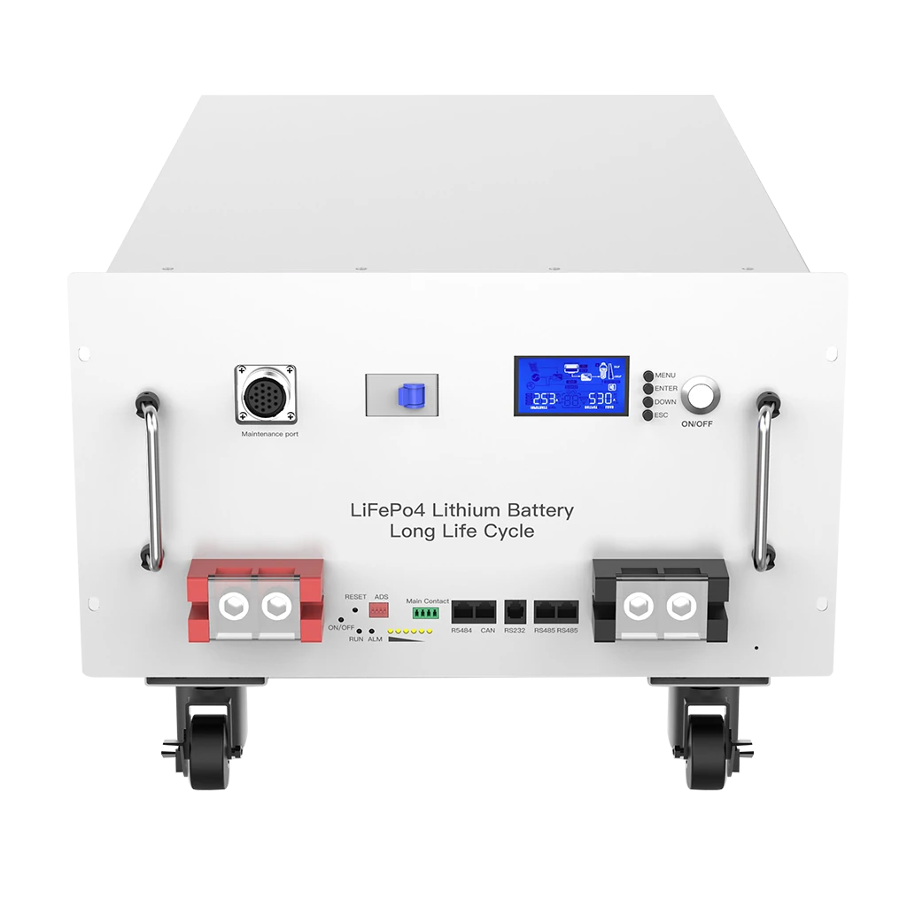

Making an inverter and lithium battery communicate requires more than connecting a communication cable. The battery BMS and inverter must match at the electrical interface, pinout, communication protocol, data rate, device role, firmware and system settings. When all seven layers match, the inverter can receive SOC, voltage, current limits, temperature and fault information directly from the battery.
The basic process is:
- Confirm the exact battery and inverter models.
- Verify their voltage and current compatibility.
- Identify whether the supported battery communication method is CAN or RS485.
- Select a communication protocol supported by both devices.
- Check the communication cable pinout.
- Configure master battery, addresses or DIP switches.
- Select the correct lithium battery/BMS profile in the inverter.
- Power up the devices in the correct sequence.
- Verify SOC, voltage, current limits and alarms on the inverter.
- Test the system under controlled charging and discharging.
For installers working with multiple inverter brands, Avepower maintains an inverter compatibility list covering supported CAN and RS485 profiles. For the communication theory behind these interfaces, see the separate battery communication, CAN, RS485 and BMS protocol guide.
What Must Match Before an Inverter and Battery Can Communicate?
Use this compatibility hierarchy:
| Compatibility Layer | What Must Be Checked | Typical Failure If Wrong |
|---|---|---|
| Battery voltage | 48V/51.2V LV or HV platform | Inverter cannot safely operate |
| Communication interface | CAN or RS485 | No communication |
| Connector | RJ45, terminal block, DB9, proprietary | Cable cannot connect correctly |
| Pinout | CAN-H/L, RS485 A/B, GND | No data or unstable communication |
| Communication speed | CAN bit rate or RS485 baud rate | Communication timeout |
| Protocol | Pylon, Victron, Growatt, GoodWe, proprietary, etc. | Devices cannot interpret messages |
| Device role | Master/slave or client/server | No valid message exchange |
| Battery address | DIP switch or software address | Multiple batteries not recognized |
| Firmware | Supported BMS and inverter revision | Partial or failed compatibility |
| Control data | CCL, DCL, CVL, SOC, alarms | Monitoring works but control does not |
Should You Use CAN or RS485 Between the Battery and Inverter?
CAN is common for closed-loop lithium battery control, while RS485 is widely used with inverter-specific or Modbus-style communication profiles.
| Feature | CAN | RS485 | Voltage-Only / Open Loop |
|---|---|---|---|
| Typical solar battery use | BMS closed-loop control | BMS communication / monitoring | Legacy or unsupported systems |
| Differential signalling | Yes | Yes | No communication |
| Multi-device support | Yes | Yes | Not applicable |
| Typical application protocol | Manufacturer-specific BMS profile | Modbus RTU or proprietary | Manual setpoints |
| SOC from BMS | Usually | Usually if supported | Estimated by inverter |
| Dynamic CCL/DCL | Usually possible | Protocol dependent | No |
| Alarm communication | Usually | Protocol dependent | No |
| Setup complexity | Medium | Medium | Low |
| Recommended choice | Use when officially supported | Use when officially supported | Only when specifically approved |
Need to Confirm Your Inverter Before Ordering Batteries?
Avepower supports solar installers, distributors, EPC contractors, project developers and OEM/ODM partners with CAN/RS485 protocol matching, inverter compatibility checks and battery configuration support.
Send your:
- Inverter brand and exact model
- Required battery capacity
- System voltage
- Inverter power
- Required battery quantity
- Project country/application
and the engineering team can review the battery configuration and communication requirements before production.
Check Avepower inverter compatibility or start a custom battery project.
How Do You Connect the Communication Cable Correctly?
First identify the dedicated BMS communication ports on both devices and compare their pin definitions before inserting the cable. An RJ45 plug describes the physical connector only; it does not guarantee that CAN-H, CAN-L, RS485-A, RS485-B or ground occupy the same pins on both devices.
A common mistake is:
Battery has RJ45 + inverter has RJ45 = standard Ethernet cable must work.
That assumption is unsafe.
Before making a cable, confirm:
- Battery-side port name.
- Inverter-side BMS port.
- CAN-H and CAN-L positions.
- RS485-A and RS485-B positions.
- Communication ground requirement.
- Shield requirement.
- Whether the cable is straight-through or crossed.
- Whether enable lines are required.
- Required termination.
- Maximum recommended cable length.
For some SMA battery-inverter installations, the manufacturer specifies shielded CAT5e-or-higher communication cable and a maximum battery communication distance of 10m.
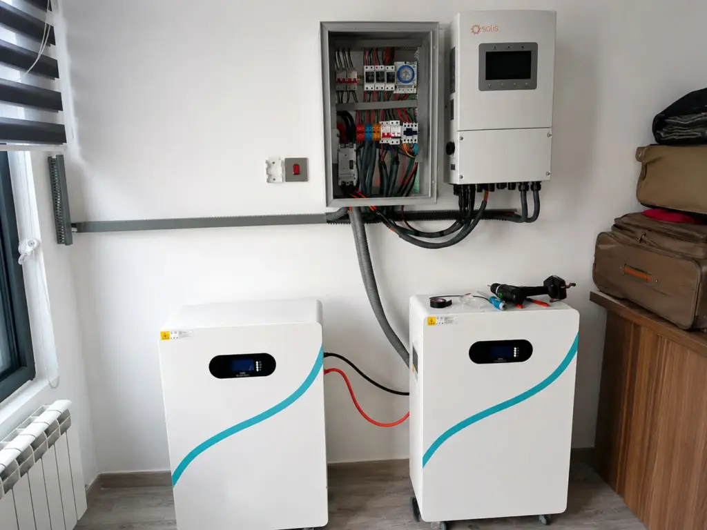
How Do You Configure the Battery BMS Protocol?
The battery must be configured to transmit a protocol the inverter actually understands. Depending on the BMS, the protocol may be selected through a touchscreen, DIP switches, Bluetooth application, PC software or factory programming. Matching only CAN or RS485 without matching the higher-level protocol will still result in failed communication.
Possible BMS profiles include inverter-specific or compatible profiles such as:
- Pylon
- Victron
- Growatt
- GoodWe
- Deye
- Solis/Ginlong
- Sofar
- SMA
- Luxpower
- SRNE
- Voltronic
- Manufacturer-specific protocols
For OEM/ODM projects where the target inverter profile is not already available, Avepower also supports BMS and communication customization as part of its custom battery development service.
How Do You Set Up Multiple Batteries With One Inverter?
When several lithium batteries are connected in parallel, they normally communicate with one another first and present the complete battery bank to the inverter through a designated master battery or controller. The parallel battery network and the inverter communication link must therefore be configured separately.
A typical topology is:
Battery 4
   │
Battery 3
   │
Battery 2
   │
Battery 1 — MASTER
   │
   │ CAN / RS485
   ▼
INVERTER
The exact wiring may instead use IN/OUT ports, daisy-chain RS485, CAN or another manufacturer-specific battery network.
Check:
- Master battery selection.
- Slave addresses.
- DIP switch configuration.
- Maximum parallel battery quantity.
- Battery-to-battery communication ports.
- Inverter communication port.
- Termination requirements.
- Firmware consistency between batteries.
Never connect every battery independently to the inverter BMS port unless the manufacturer specifically designs the system that way.
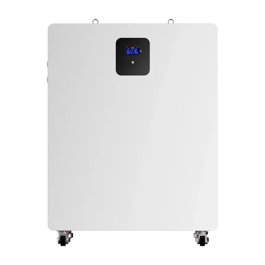
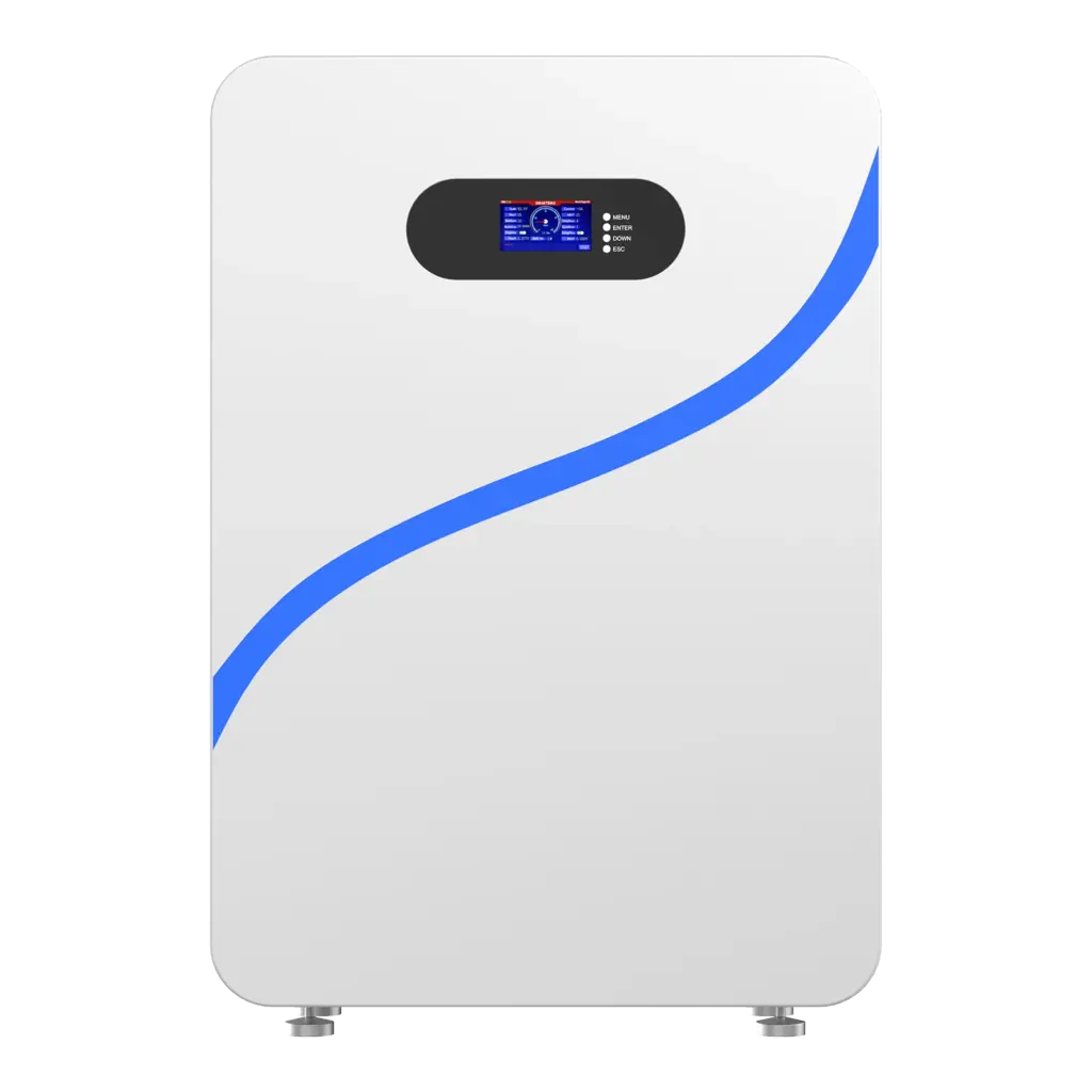
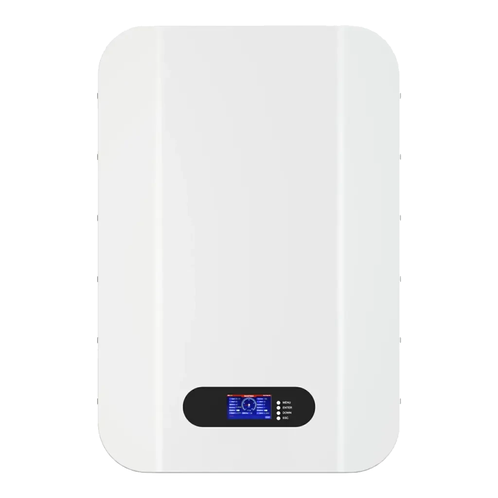
Avepower’s wall-mounted 5.12kWh battery, for example, supports CAN, RS485 and RS232 communication and up to 16 batteries in parallel for suitable project configurations.
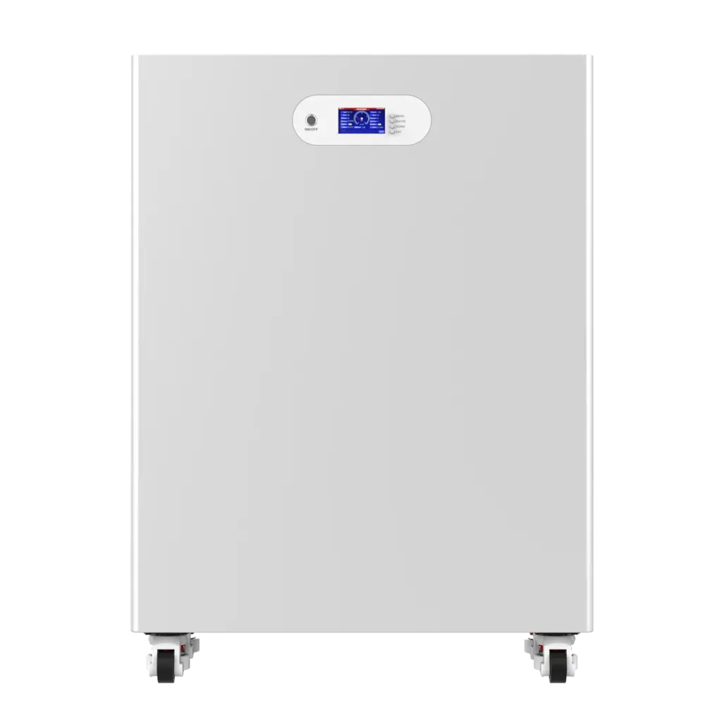
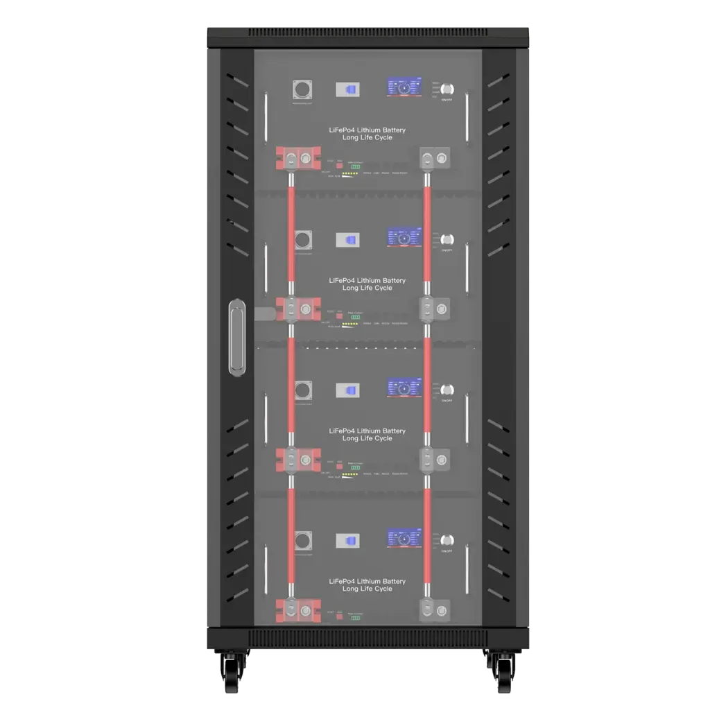
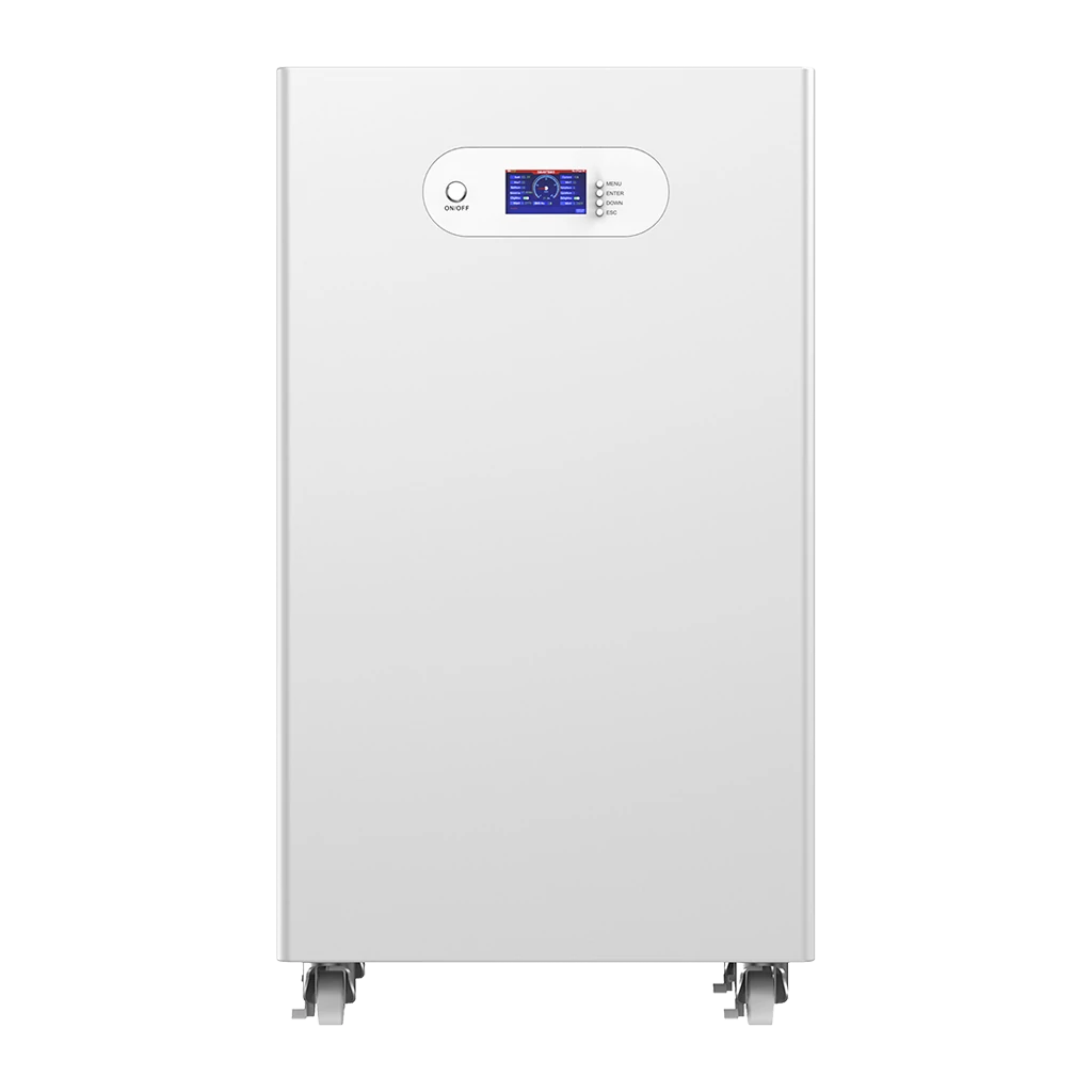
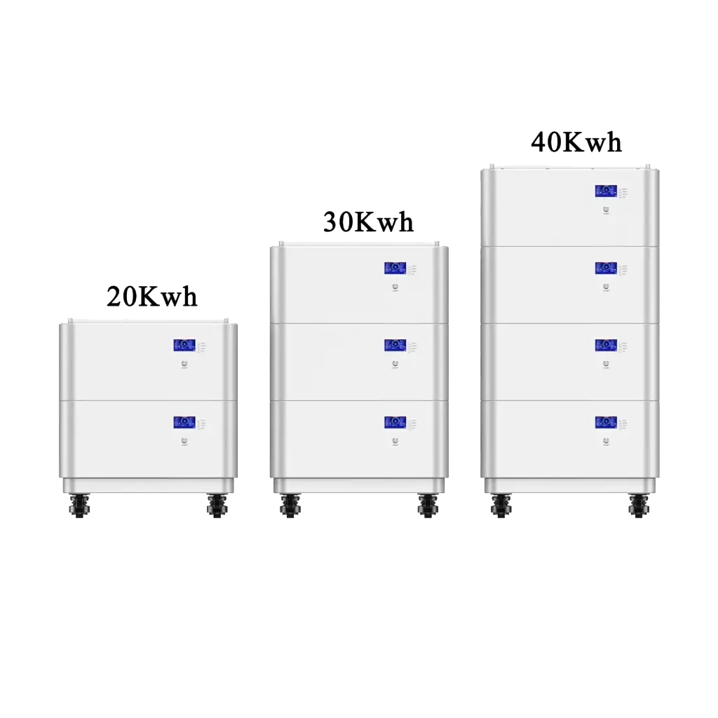
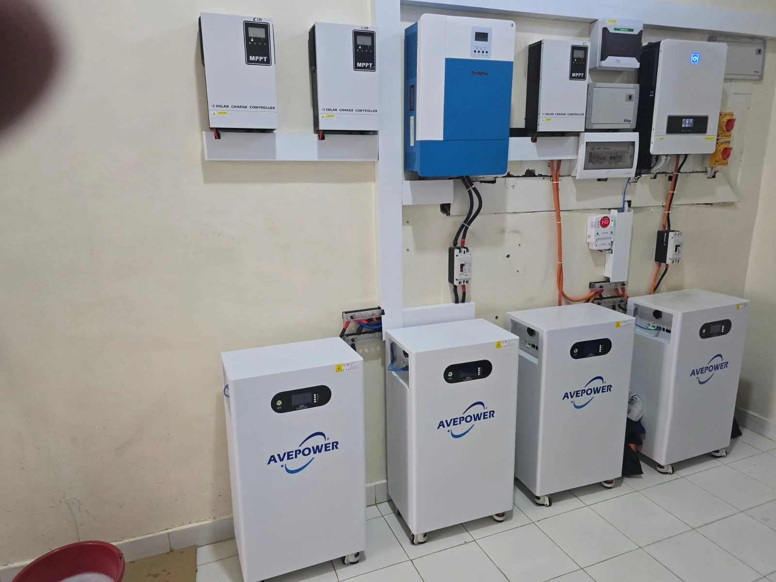
For larger modular projects, Avepower also provides 20–40kWh stackable LiFePO4 battery systems with CAN, RS485 and RS232 integration support.
Does a CAN Bus Need a 120-Ohm Termination Resistor?
CAN networks normally require correct termination at the physical ends of the communication bus, but installers should first determine whether the termination is already built into the battery, inverter or selectable through DIP switches. Adding extra resistors without checking the system architecture can create its own communication problems.
Why Does Electrical Sizing Still Matter After Communication Works?
Successful BMS communication does not prove that the battery is electrically large enough for the inverter. The battery must also support the inverter’s DC current, surge requirements and voltage range. Communication compatibility and electrical compatibility should always be verified as two separate engineering checks.
For an approximate inverter DC current:
Battery current ≈ inverter output power ÷ battery voltage ÷ inverter efficiency
Consider:
- Inverter output = 5,000W
- Battery nominal voltage = 51.2V
- Assumed inverter efficiency = 92%
Then:
5,000 ÷ 51.2 ÷ 0.92 ≈ 106A
So the battery system should safely provide more than approximately 106A DC at full 5kW output, with suitable engineering allowance for operating voltage, surge loads, temperature, wiring and BMS derating.
If the BMS allows only 80A discharge:
51.2V × 80A = 4.096kW DC
That battery cannot continuously support a 5kW AC load merely because CAN communication works.
For more detailed current calculations, see Avepower’s battery discharge current guide.
What Does a Real Battery Communication Project Look Like?
Large commercial battery systems show why communication should be designed as an architecture rather than a single CAN cable. Individual battery-management units collect cell and module data, higher-level controllers coordinate complete clusters, and CAN or RS485 networks carry operating information and protection signals toward the PCS, EMS or other supervisory equipment.
Avepower’s published Lithuanian project provides a practical example.
The system configuration was:
| Parameter | Project Value |
|---|---|
| Total energy | 522.496kWh |
| Nominal DC voltage | 832V |
| Capacity | 628Ah |
| Battery cabinets | 4 × 42U |
| Battery clusters | 2 |
| Packs per cluster | 13 |
| Energy per pack | 20.096kWh |
| Continuous current | 200A |
| Communication | CAN / RS485 |
| Management architecture | BMU + BCU |
The energy calculation is:
20.096kWh × 13 packs × 2 clusters = 522.496kWh
But energy capacity is only one part of the system.
The project used BMU/BCU coordination and CAN/RS485 communication so that cell and pack information could be managed at higher system levels rather than treating 26 battery packs as independent devices.
Avepower’s published case reports ±0.2% full-scale voltage sampling accuracy together with CAN/RS485 communication and the two-cluster architecture. See the full 522.5kWh Lithuania ESS case study
The practical lesson for installers and EPCs is:
The larger the battery system becomes, the more important communication architecture, addressing, hierarchy and commissioning become.
Make Your Battery and Inverter Communicate Before the Project Reaches Site
Reliable battery-inverter integration should be confirmed during system design—not discovered during commissioning.
Avepower supports solar installers, distributors, EPC contractors and OEM/ODM partners with LiFePO4 battery selection, inverter compatibility checks, CAN/RS485 protocol matching, BMS configuration and project-based battery development.
With a 20,000m² manufacturing base, 50+ R&D engineers and dedicated OEM/ODM engineering support, Avepower can evaluate the battery voltage, capacity, charge/discharge current, inverter model and communication requirements before production.
Send us your inverter brand and model, required kWh, inverter power, application and target market.
Take Control of Your Energy with Avepower!
Reliable home solar battery solutions with OEM/ODM customization and in-house manufacturing, tailored to the needs of distributors, installers, and energy partners.
FAQ
Only if both manufacturers specify the same straight-through RJ45 pinout. RJ45 is only the connector type; CAN-H, CAN-L, RS485-A and RS485-B may be assigned to different pins.
The physical communication link may be active while the protocol profile or data mapping is incorrect. Check the selected battery protocol, firmware version and BMS configuration.
Yes. CAN-H and CAN-L must be connected according to the specified pinout. Incorrect wiring can prevent communication completely.
Not universally. Use the interface and protocol officially supported by the inverter–battery combination. CAN is very common for closed-loop BMS control, while RS485 is widely used for device communication, monitoring and Modbus-based integration.
Check battery addresses, master/slave configuration, parallel communication cables, DIP switches, firmware consistency and termination. Multi-battery networks usually require a defined communication topology.
Provide the inverter brand, exact model, battery voltage, required capacity, system power, communication interface and project configuration. The engineering team can then verify protocol, pinout and BMS settings.
Not universally. CAN is widely used for closed-loop BMS communication, while RS485 is also common in energy storage systems. The correct choice is the interface and protocol officially supported by both devices.
BMS communication is the data link that allows the inverter to receive battery information such as SOC, voltage, temperature, charge limits, discharge limits and fault status from the battery management system.
Typical causes include an incorrect cable, reversed CAN or RS485 signals, wrong protocol, incorrect CAN bit rate or RS485 settings, wrong battery address, incorrect master battery selection, firmware incompatibility or missing termination.