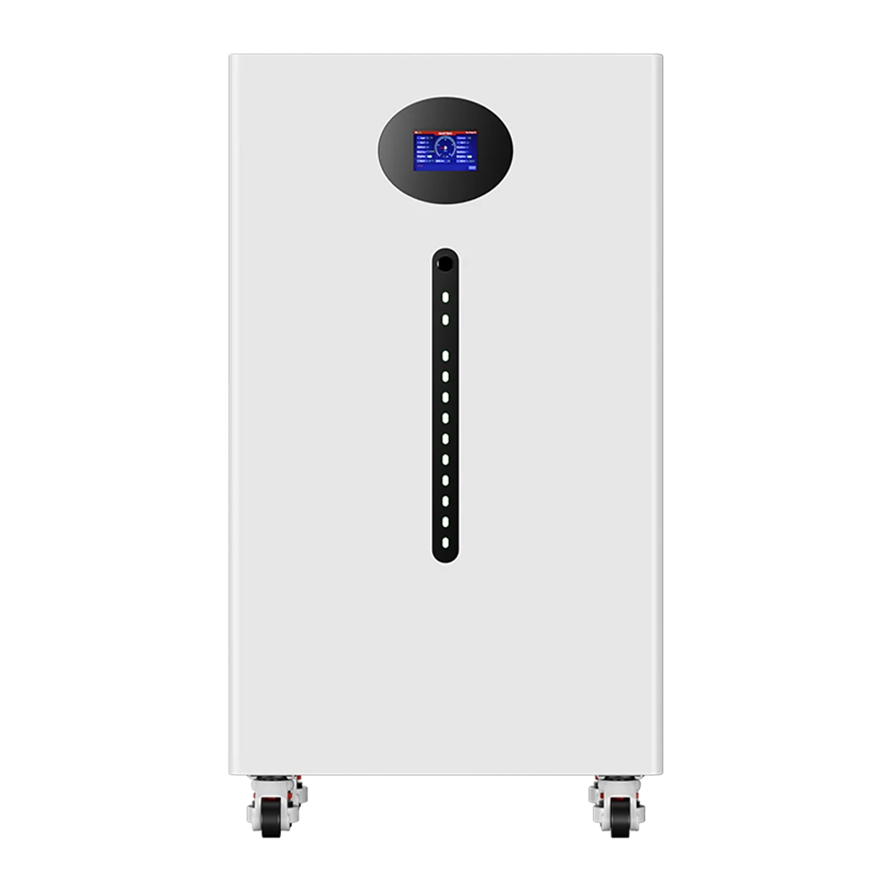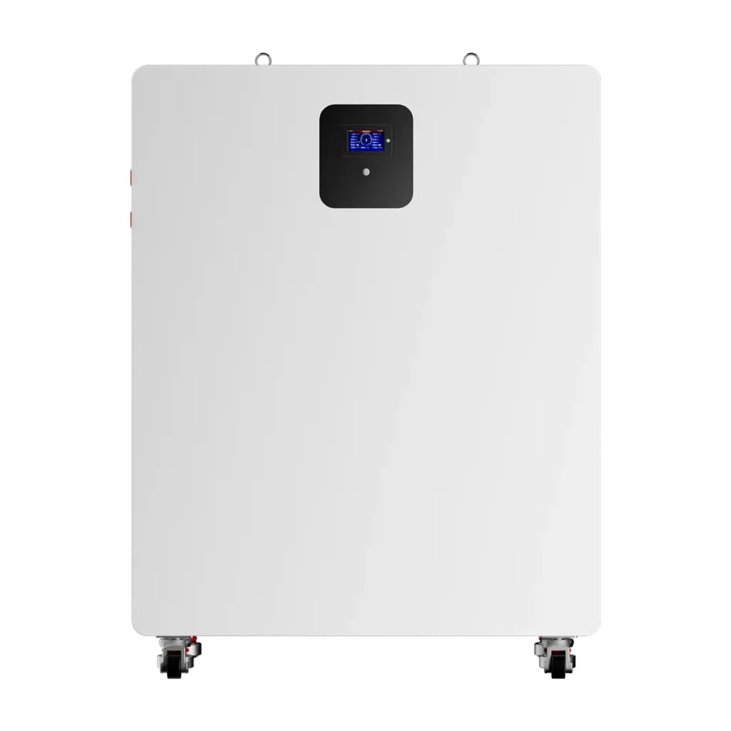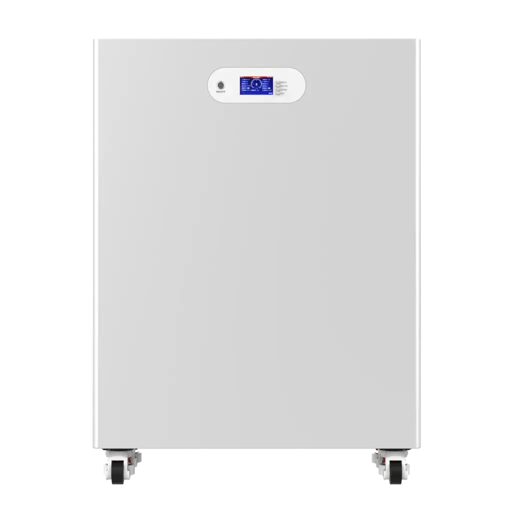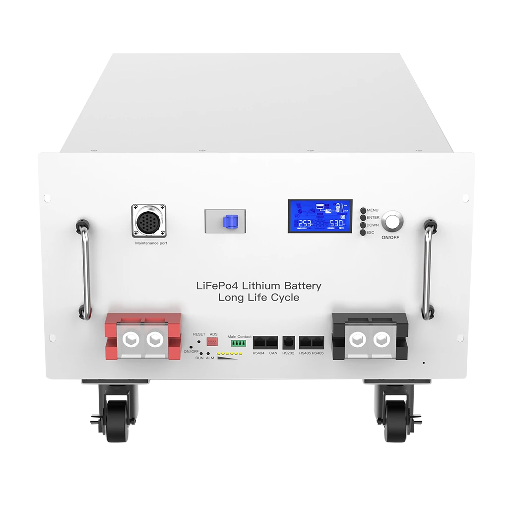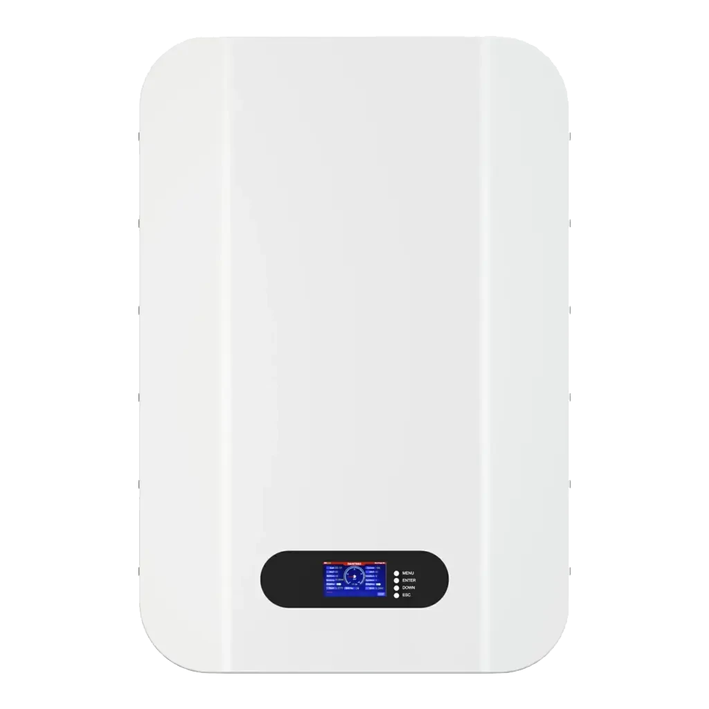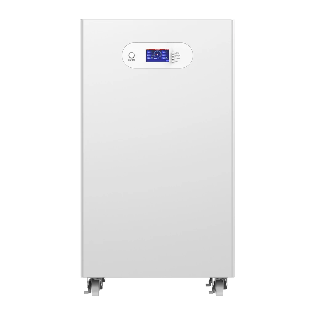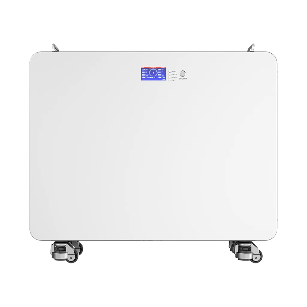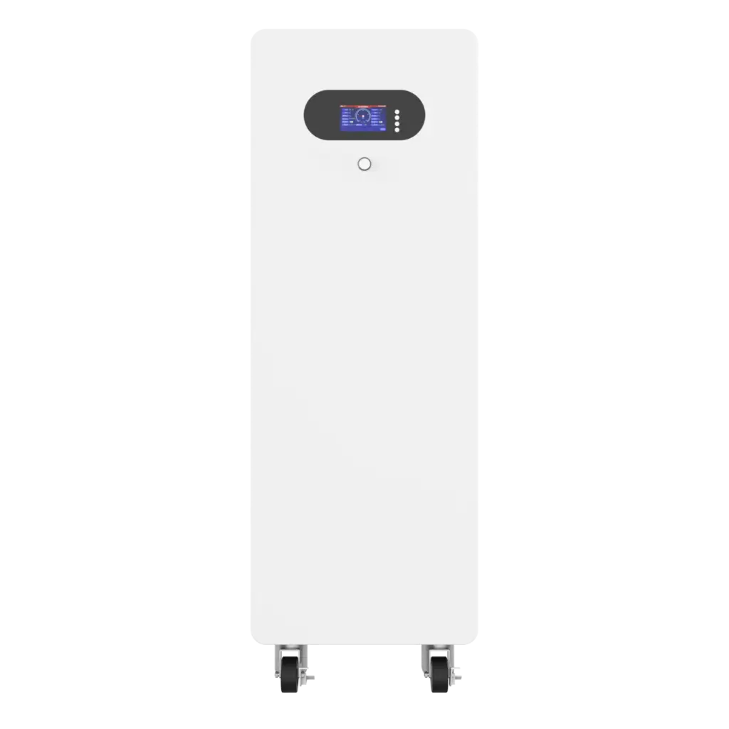

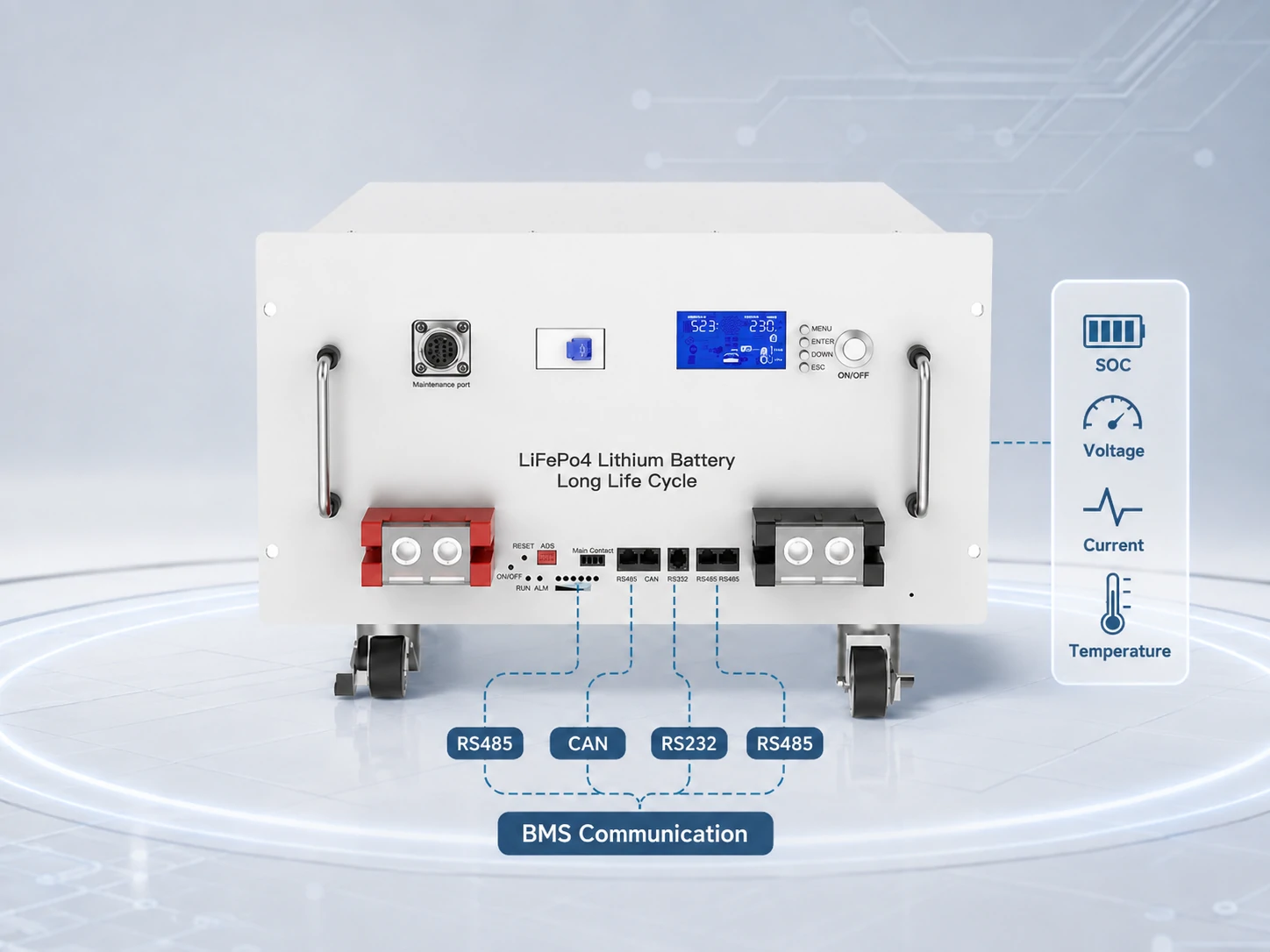
An RS485 lithium battery can exchange operating data with an inverter, EMS or monitoring device, but an RS485 port alone does not guarantee communication. Successful integration also requires compatible wiring, pin definitions, serial settings, device addressing, message protocol, data mapping and firmware.
If you are selecting a battery for an existing inverter, start with the manufacturer’s protocol documentation rather than the connector. Avepower also maintains an inverter compatibility list for installers evaluating supported communication combinations.
What Is an RS485 Lithium Battery?
An RS485 lithium battery is a lithium battery—commonly LiFePO4 in stationary energy storage—whose BMS includes an RS485 electrical interface for exchanging operating information with an inverter, EMS, display, gateway or service tool. RS485 describes how electrical signals travel between devices; it does not by itself define what the transmitted battery data means.
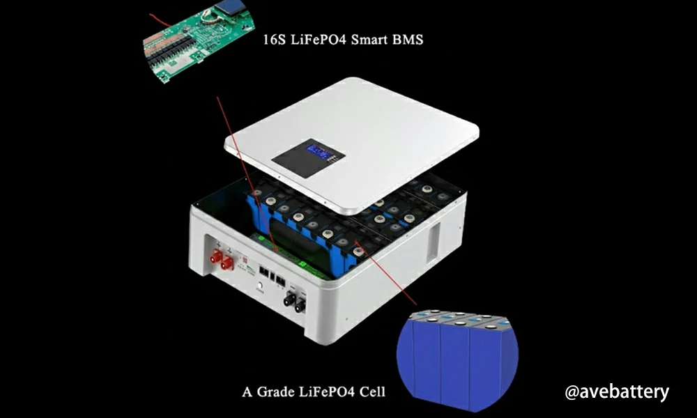
Inside a modern energy-storage battery, the battery management system monitors parameters such as cell voltage, pack voltage, current and temperature. Depending on the BMS and its communication protocol, some of this information can be made available to other equipment through RS485.
For a wider explanation of these technologies, see Avepower’s battery communication guide.
What Data Can an RS485 Lithium Battery Send to an Inverter?
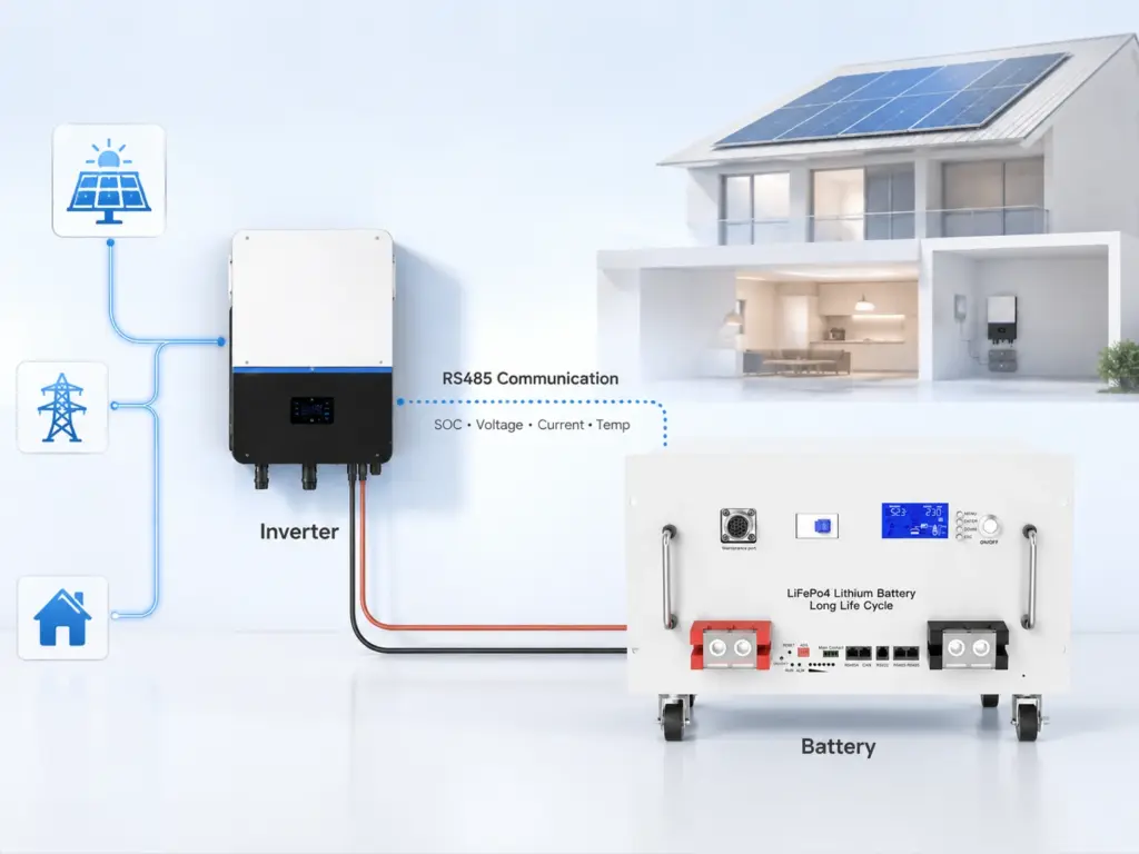
RS485 can carry much more useful information than battery voltage alone when the BMS protocol supports it. A closed-loop integration may give the inverter access to SOC, pack voltage, current, temperature, alarms and dynamic charge or discharge limits, allowing the inverter to adjust its operation according to the battery’s actual condition.
| BMS Data | What It Represents | Possible Inverter Use |
|---|---|---|
| SOC | State of charge | Backup reserve and charge/discharge decisions |
| SOH | Battery condition estimate | Maintenance and derating |
| Pack voltage | Total battery DC voltage | Operating-range verification |
| Battery current | Actual charge/discharge current | Power monitoring |
| Cell/pack temperature | Thermal condition | Derating or shutdown |
| CCL | Charge Current Limit | Reduce requested charging current |
| DCL | Discharge Current Limit | Reduce requested discharge power |
| Charge voltage limit | Maximum permitted charge voltage | Charger control |
| Charge enable | Permission to charge | Start or stop charging |
| Discharge enable | Permission to discharge | Start or stop discharge |
| Alarm/fault status | BMS protection condition | Alarm, derating or shutdown |
| Communication status | BMS availability | Normal operation or fail-safe response |
Users who need more information about SOC and SOH can also refer to Avepower’s battery SOC and SOH guide.
Build an RS485 Lithium Battery System Around Verified Compatibility
Choosing an RS485 lithium battery should not end with finding an RS485 label on the front panel. A reliable energy-storage system requires the battery voltage, current capability, BMS protocol, inverter profile, pinout, addressing, firmware and project architecture to work together.
Avepower develops LiFePO4 battery systems for residential, commercial and project applications with CAN, RS485 and RS232 communication options. Its 20,000+ m² production base, 15+ production lines and 50+ R&D and engineering staff, alongside BMS/firmware setup and finished-pack testing processes.
Planning a Project?
Send Avepower your inverter brand and exact model, firmware version, battery voltage, required capacity, charge/discharge current, project country and expected order volume. The engineering team can review the inverter compatibility requirements, communication protocol and battery architecture before sample validation or bulk production.
Is RS485 the Same as Modbus?
No. RS485 and Modbus describe different parts of a communication system. RS485 primarily defines the electrical signaling used to move data over a serial network, while Modbus defines how devices can structure and exchange messages. Modbus RTU commonly operates over RS485, but an RS485 lithium battery may instead use a manufacturer-specific protocol.
| Layer | Example | What It Defines |
|---|---|---|
| Application/message layer | Modbus or manufacturer battery protocol | Meaning and structure of information |
| Serial communication layer | Modbus RTU or proprietary framing | Frames, addresses and error checking |
| Physical electrical layer | RS485 | Electrical transmission between devices |
| Connector/cable | RJ45, terminal block, proprietary connector | Physical connection and pin positions |
RS485 vs CAN vs RS232 vs WiFi and Bluetooth: Which Is Better for a Lithium Battery?
RS485 and CAN are normally used for wired system-level communication, while RS232 is more commonly suited to local service or point-to-point access and Bluetooth/WiFi mainly support monitoring.
| Communication | Typical Battery Role | Multi-Device Use | Typical Strength | Main Limitation |
|---|---|---|---|---|
| RS485 | Inverter, battery bank, EMS, meter, monitoring | Yes | Differential signaling and flexible industrial integration | Protocol is not defined by RS485 |
| CAN | Battery-to-inverter / BCU / controller | Yes | Strong real-time bus architecture | Device profiles must still match |
| RS232 | PC, service tool, local configuration | Usually point-to-point | Simple commissioning interface | Less suitable for multi-node networks |
| Bluetooth | Local phone monitoring | No system bus | Easy local access | Not normally inverter control link |
| WiFi | App/cloud monitoring | Network based | Remote monitoring | Network connection is different from BMS control |
How Do You Connect an RS485 Lithium Battery to a Solar Inverter?
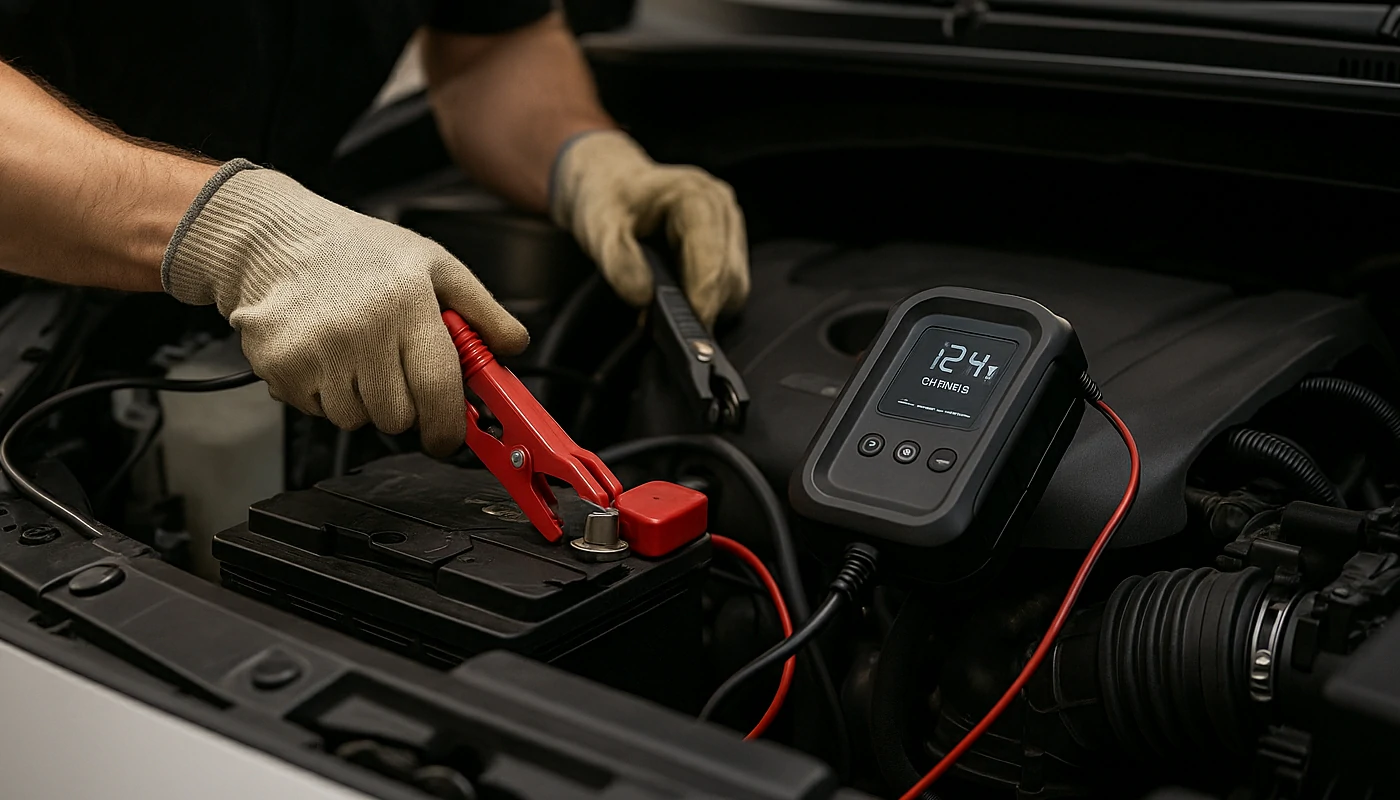
Connect an RS485 lithium battery only after confirming the battery voltage, approved inverter profile, communication connector, pinout, protocol and startup sequence. A successful installation should be verified through live SOC, voltage, current, temperature and communication status—not simply by seeing that the battery and inverter have powered on.
A practical commissioning sequence is:
Step 1: Isolate the System
Shut down the battery, inverter, charger and other relevant sources according to the equipment manuals before changing communication wiring.
Step 2: Confirm Inverter Compatibility
Record:
- Inverter brand
- Exact inverter model
- Firmware version
- Battery voltage range
- Supported battery/BMS profiles
- CAN or RS485 requirement
Do this before making communication cables.
Step 3: Verify the Communication port
Many inverters contain several physically similar sockets for:
- Battery CAN
- Battery RS485
- Meter RS485
- Parallel inverter communication
- Service communication
Using the wrong RJ45 socket is a common commissioning mistake.
Step 4: Verify Every Communication pin
Match the battery manual to the inverter manual.
Do not infer the pinout from connector appearance.
Step 5: Configure Battery Addresses
If multiple batteries are installed, assign the required DIP-switch or software addresses and establish the primary battery according to the battery architecture.
Step 6: Select the Correct Battery Protocol
Configure the inverter’s lithium battery profile or manufacturer protocol.
If required, configure serial parameters such as baud rate and address.
Step 7: Follow the Specified Startup Sequence
Some systems require the batteries to start before the inverter; others have their own commissioning procedure.
Use the current product manual.
Step 8: Verify Real Operating Data
A communication link should not be considered commissioned until meaningful values are visible.
A practical pass/fail check is:
| Commissioning Check | Pass Condition |
|---|---|
| SOC | Inverter displays plausible battery SOC |
| Battery voltage | Inverter value approximately agrees with BMS reading |
| Current | Direction and magnitude respond correctly to load/charge |
| Temperature | Valid battery temperature data appears if supported |
| Communication alarm | No persistent communication fault |
| Charge/discharge permission | Changes correctly when BMS protection requires it |
| Dynamic current limit | Inverter responds correctly if protocol supports CCL/DCL |
| Multiple batteries | Correct total capacity/status is visible where supported |
Why Is My RS485 Lithium Battery Not Communicating With the Inverter?
Most RS485 battery communication failures can be narrowed down systematically rather than solved by randomly changing inverter settings. Start by checking the correct communication port, pinout and protocol, then verify serial parameters and addresses before investigating signal integrity, firmware or data-mapping issues. A powered battery does not prove that its communication link is working.
Recommended Troubleshooting Sequence
- Verify that the battery itself is powered and the BMS has no internal fault.
- Confirm the inverter’s correct BMS communication port.
- Confirm RS485 rather than CAN.
- Verify cable continuity and pin mapping.
- Check A/B assignments against both manuals.
- Select the correct inverter battery profile.
- Configure battery address and master/slave settings.
- Verify baud rate and serial parameters.
- Check firmware versions.
- Test first with one battery and a short approved cable.
- Add parallel modules only after the first connection is stable.
- Record final firmware, DIP and protocol settings for future service.
This provides substantially more diagnostic value than repeatedly swapping cables without checking the communication stack.
How Can You Verify RS485 Communication Before Full Commissioning?
RS485 communication should be validated under real operating conditions rather than declared successful after the inverter first detects the battery. Good commissioning verifies stable communication, plausible battery values, correct current direction, changing SOC, BMS permissions, dynamic limits where supported, alarm behavior and safe response when communication is intentionally lost.
Start by comparing values shown on different system interfaces.
For example:
| Parameter | BMS Reading | Inverter Reading | Result |
|---|---|---|---|
| Pack voltage | 52.4 V | 52.3 V | Plausible |
| SOC | 68% | 68% | Match |
| Discharge current | 24.7 A | 24.5 A | Plausible |
| Battery temperature | 27°C | 27°C | Match |
Small differences can result from measurement timing and sensor accuracy. Large or consistently scaled errors—such as 5.24 V appearing when the battery is near 52.4 V—may indicate an incorrect scaling or data interpretation issue rather than a physical RS485 fault.
Where manufacturer documentation permits, service engineers may also use:
- Manufacturer diagnostic software
- BMS monitoring tools
- Protocol analyzers
- Approved USB-to-RS485 adapters
- Modbus diagnostic software for documented Modbus devices
Do not write to undocumented BMS registers simply to test communication. Some addresses can affect battery configuration or protection behavior.
What Does a Real RS485 Battery Project Look Like?
Large battery projects demonstrate why communication architecture matters beyond simply choosing an RS485 connector. Avepower’s documented Lithuania project uses a 522.496kWh high-voltage battery system with BMU/BCU control architecture and CAN/RS485 communication, showing how battery information must be aggregated and managed as multiple packs and clusters are combined into one energy-storage system.
The documented system consists of:
- 522.496 kWh total energy
- 832 V DC system
- 2 battery clusters in parallel
- 13 battery packs per cluster
- 20.096 kWh per battery pack
- 200 A continuous system current
- BMU/BCU battery management architecture
- CAN/RS485 communication
The capacity calculation is straightforward:
20.096 kWh/pack × 13 packs/cluster × 2 clusters = 522.496 kWh
Avepower reports ±0.2% FS battery voltage sampling accuracy for the project’s battery-management architecture and identifies CAN/RS485 as part of its communication design. Full project details are available in the Lithuania 522.5kWh high-voltage ESS case study.
The decision value for an installer or project developer is more important than the capacity number itself:
As the number of battery packs increases, communication becomes an architecture problem.
A large system may require individual pack BMUs, cluster-level controllers and a higher-level BCU or EMS rather than having every battery independently communicate with the PCS.
That is one reason communication design should be defined during system engineering, not after battery cabinets arrive on site.
Which Avepower RS485 Lithium Batteries Fit Different Storage Projects?
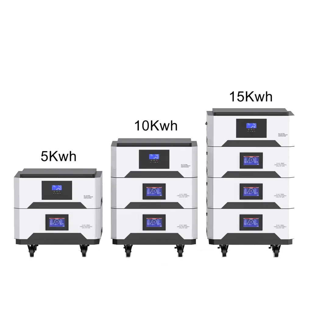
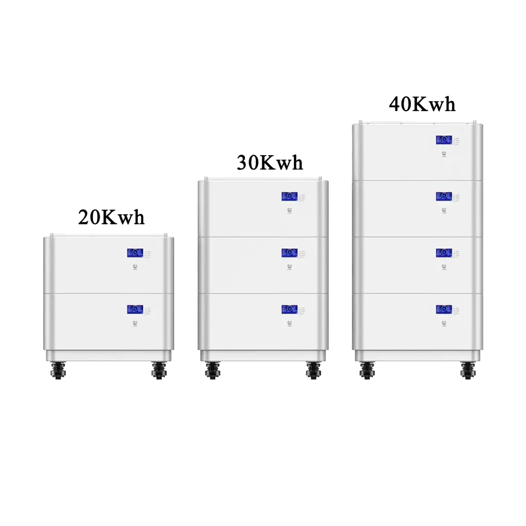
Avepower uses RS485 alongside CAN and RS232 across several LiFePO4 energy-storage products, allowing installers to select the battery architecture according to capacity, current and installation requirements. The most important selection step remains protocol verification with the target inverter, especially for projects that require closed-loop BMS communication rather than simple voltage-based operation.
Examples include:
| Battery | Key Specification | Communication | Expansion | Typical Project Fit |
|---|---|---|---|---|
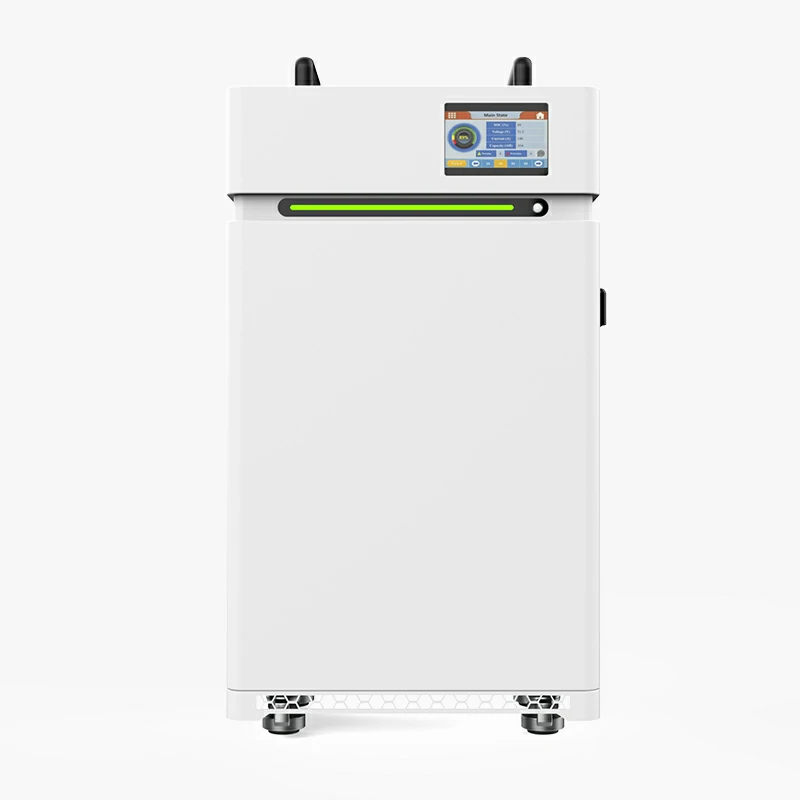
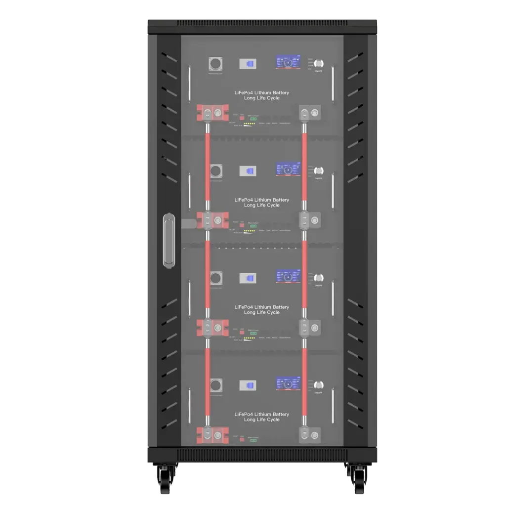
| 15kWh Rack Battery | 48V, 280Ah, 15kWh | CAN / RS485 / RS232 | Up to 16 parallel | Rack-based residential and small commercial storage |
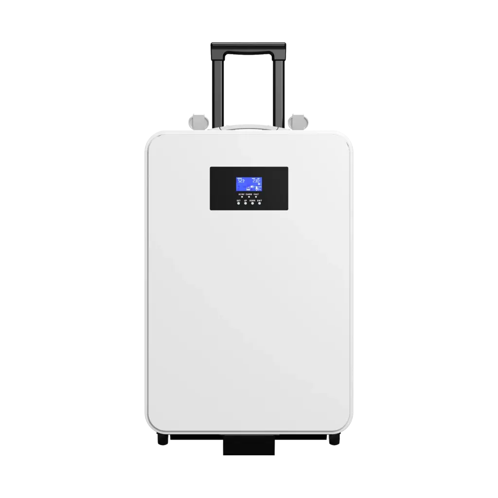
| 16kWh Vertical Battery | 51.2V, 314Ah, about 16kWh | CAN / RS485 / RS232 | Up to 16 parallel | High-consumption homes and installer projects |
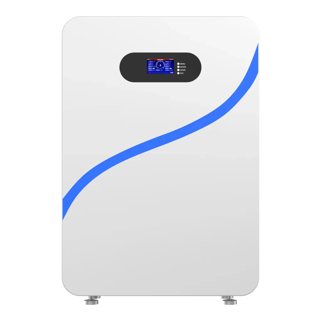
| 10kWh Wall Battery | 48V-class, 200Ah, 10kWh | CAN / RS485 / RS232 | Up to 16 parallel | Residential solar and backup |
| 30kWh Vertical Battery | 48V-class, 600Ah, 30kWh | CAN / RS485 / RS232 | Project dependent | Larger residential and small commercial systems |
| 50kWh Vertical Battery | 51.2V, 942Ah, 50kWh | CAN / RS485 / RS232 | Up to 16 parallel | Higher-capacity low-voltage projects |
For example, the current Avepower 15kWh rack battery specification lists up to 100A charging, 200A continuous discharge and up to 16 units in parallel, while the 16kWh vertical model specifies a 51.2V 314Ah architecture and CAN/RS485/RS232 communication.
For a new installation, send the exact inverter brand and model to the battery supplier rather than choosing one of these products from communication-port specifications alone.
Take Control of Your Energy with Avepower!
Reliable home solar battery solutions with OEM/ODM customization and in-house manufacturing, tailored to the needs of distributors, installers, and energy partners.
Final Answer: Is an RS485 Lithium Battery the Right Choice?
An RS485 lithium battery is a good choice when your inverter, BMS and system architecture have a documented RS485 communication path. The deciding factor is not the RS485 connector itself but whether the two devices share the required wiring, serial settings, protocol, data definitions and firmware, and whether that integration has been verified under real operating conditions.
Avepower develops LiFePO4 battery systems with CAN, RS485 and RS232 communication across residential and project-based storage platforms. If you are evaluating an RS485 battery for a specific inverter, provide:
- Inverter brand and model
- Required battery voltage
- Required capacity
- Number of battery units
- Project country
- Communication protocol or inverter battery profile
- Required certification documents
Our engineering team can use these details to verify the communication configuration before production.
Check Avepower Inverter Compatibility or Start a Custom Battery Project to discuss an RS485 LiFePO4 battery configuration for your application.
FAQ
No. RS485 defines an electrical communication interface. Modbus RTU is one protocol commonly carried over serial RS485 networks, but lithium battery manufacturers may also use proprietary RS485 message formats. The official Modbus serial specification distinguishes these layers.
RS485 signals can be assigned to an RJ45 connector, but an RJ45 connector does not mean Ethernet and does not establish a universal battery pinout.
Baud rate is determined by the BMS communication implementation. Check the battery protocol document and inverter configuration instead of assuming a value such as 9600 or 19200 baud.
CAN and RS485 can both be suitable for battery communication. The better choice is normally the interface and protocol that the exact battery BMS and inverter have been designed and validated to use together.
Do not use the RS485 electrical-layer node limit as the battery-system parallel limit. The BMS, addressing scheme, current architecture and manufacturer specification determine the permitted number of battery modules. For example, Avepower’s 48V 280Ah rack battery publishes a maximum of 16 parallel units.
Normally not when RS485 is being used for inverter/BMS control. Bluetooth and WiFi are commonly used for local or remote monitoring, while RS485 or CAN may provide the wired inverter-control connection.