
Battery chemistry often gets most of the attention in energy storage discussions. But in a real battery energy storage system, the battery does not work alone. The component that decides how energy moves between the battery, the grid, solar power, generators and local loads is the Power Conversion System, commonly called the PCS.
A Power Conversion System is not just another name for an inverter. In a battery energy storage system, the PCS is a bidirectional power electronic system that converts electricity between DC and AC, controls active and reactive power, manages voltage and frequency behavior, communicates with the BMS and EMS, and helps the system operate safely under changing grid or load conditions.
This guide explains what a Power Conversion System is, how it works in BESS, how it differs from a standard inverter, which PCS specifications matter most, and how installers, EPCs, OEM brands and project developers should evaluate PCS matching before building a storage system.
Quick Answer: What Is a Power Conversion System?
A Power Conversion System PCS is a bidirectional power electronic device used in battery energy storage systems. It converts AC power to DC power when charging batteries and converts DC power back to AC power when discharging batteries to loads or the grid.
A PCS also controls voltage, frequency, active power, reactive power, power factor, grid synchronization, protection and communication with the BMS and EMS. In modern BESS projects, the PCS is not just an inverter. It is the control bridge between the battery, the electrical load and the grid.
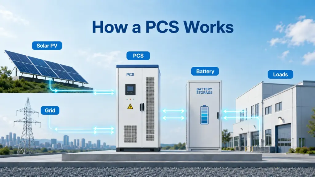
How a Power Conversion System Works
A PCS performs two main conversion processes: rectification and inversion.
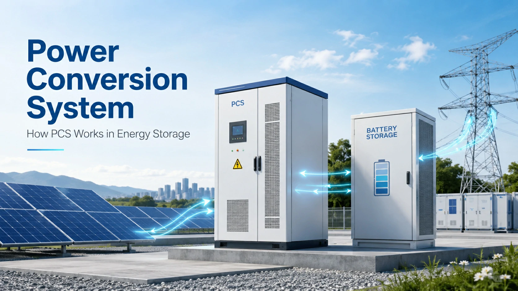
During charging, the PCS converts AC power from the grid, generator or AC-coupled renewable source into DC power for the battery. During discharging, it converts DC power from the battery into AC power for local loads or grid export.
The power flow usually looks like this:
Charging mode
Grid or AC source → PCS → DC battery system
Discharging mode
DC battery system → PCS → AC loads or grid
The process sounds simple, but modern PCS equipment does much more than basic conversion. It continuously measures voltage, current, frequency, temperature, power factor, system status and grid conditions. Based on these signals, it adjusts switching behavior in milliseconds.
Many PCS designs use IGBT, MOSFET or SiC semiconductor devices.
PCS vs Inverter: What Is the Difference?
A standard inverter usually converts DC power into AC power. A solar inverter, for example, converts DC electricity from PV panels into AC electricity for home use or grid export.
A Power Conversion System is broader. It is designed for bidirectional energy storage operation, battery charge and discharge control, grid support, protection, communication and coordination with BMS and EMS.
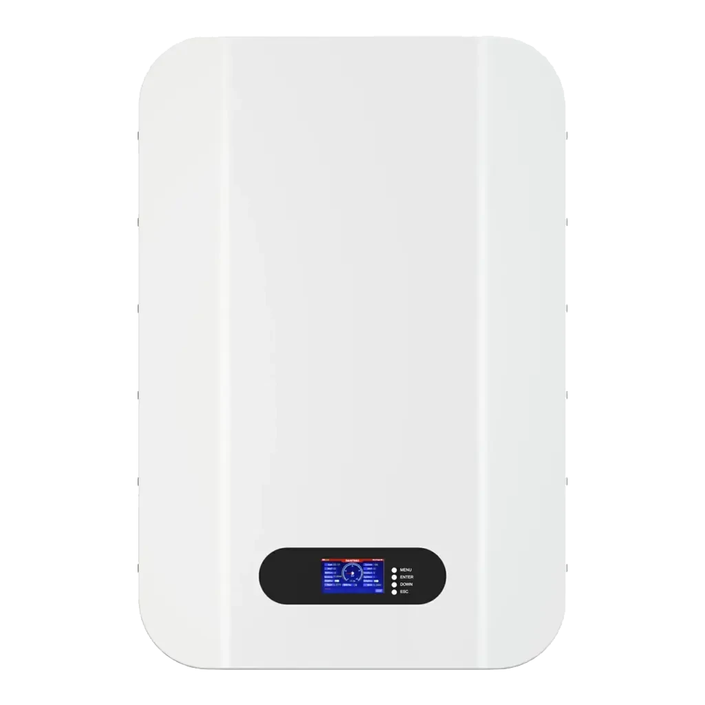
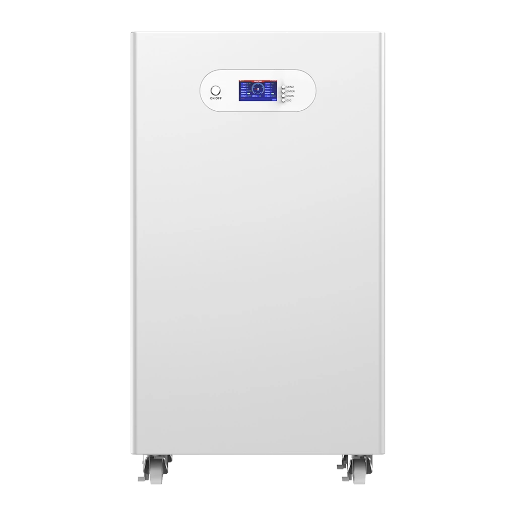
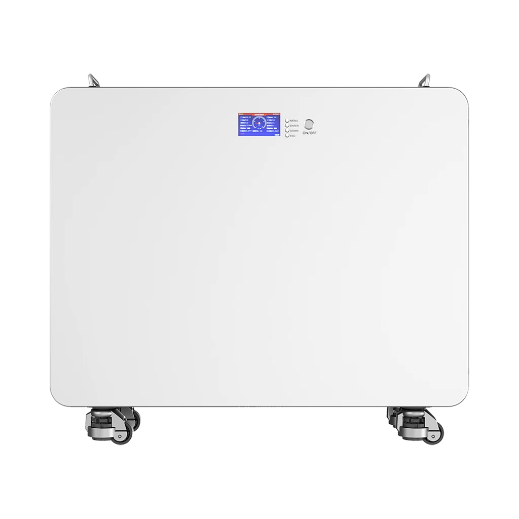
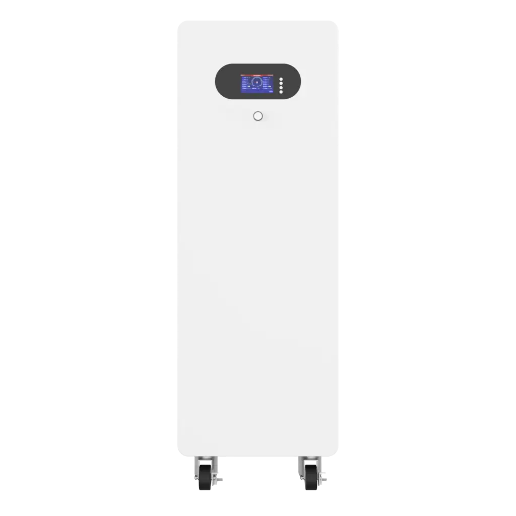
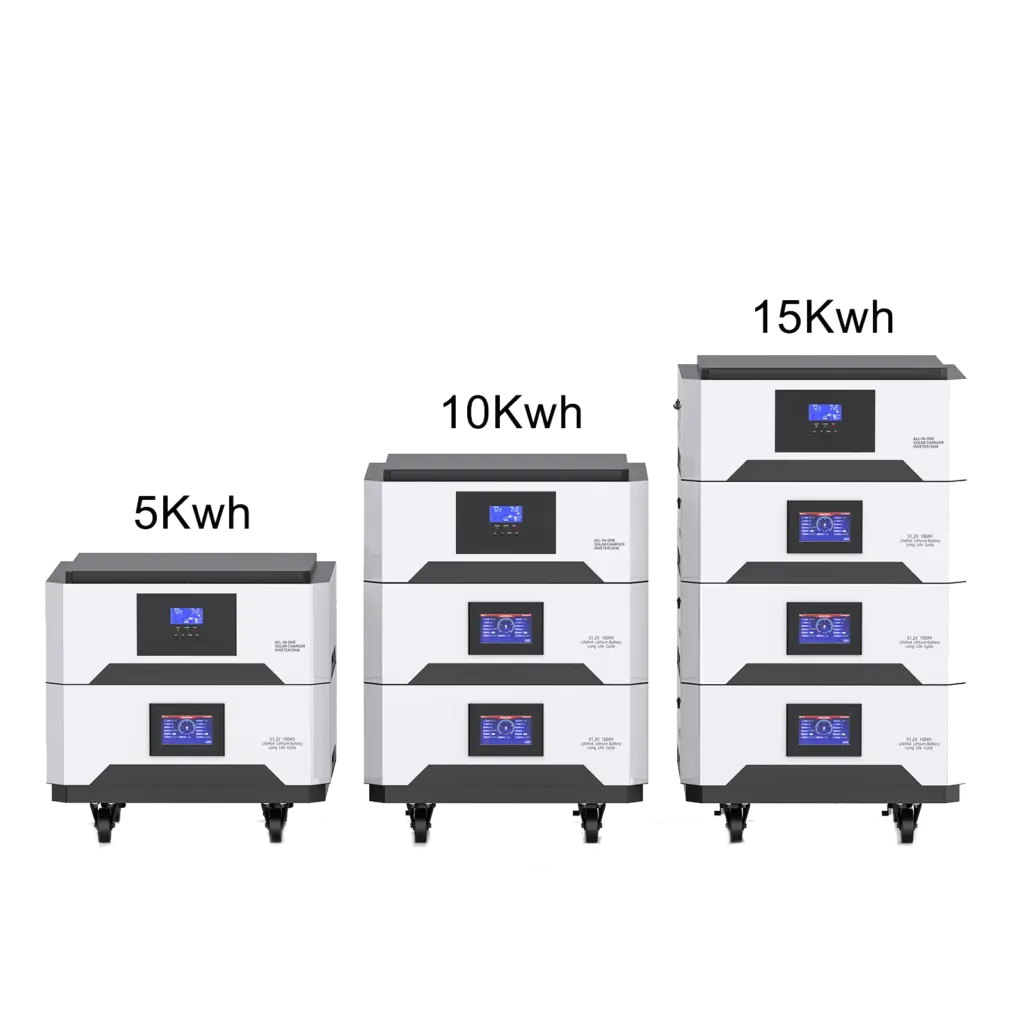
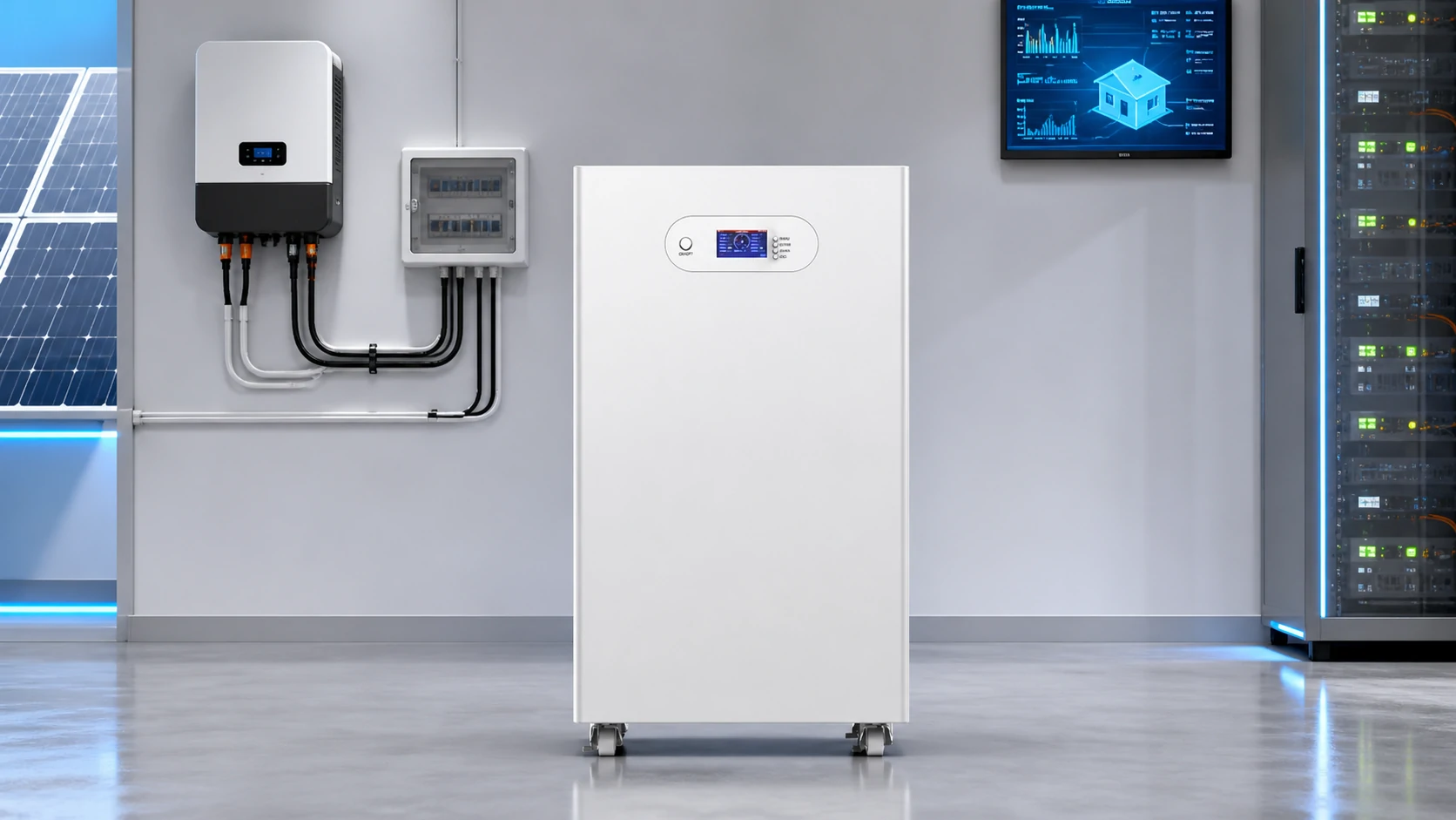
In small residential systems, the PCS function may be integrated into a hybrid inverter or all-in-one battery system. For example, an Avepower all-in-one home battery energy storage system integrates battery storage and inverter functionality in one compact solution for home solar storage and backup power.
| Feature | Power Conversion System PCS | Standard Solar Inverter |
|---|---|---|
| Power flow | Bidirectional AC ↔ DC | Usually DC → AC |
| Main application | Battery energy storage system | Solar PV generation |
| Battery coordination | Deep integration with BMS and EMS | Limited or external |
| Grid services | Active/reactive power, frequency support, voltage support | Basic grid export and protection |
| Typical use | C&I BESS, utility BESS, microgrid, backup system | Rooftop solar, PV plant |
| Control role | Energy storage power control center | PV power conversion device |
A PCS can be considered a specialized bidirectional inverter for energy storage, but in professional BESS design, it is better to treat it as a complete conversion and control system rather than a simple inverter.
For readers who want to understand system architecture further, Avepower’s guide to AC vs DC coupling explains how different conversion paths affect solar and battery system efficiency.
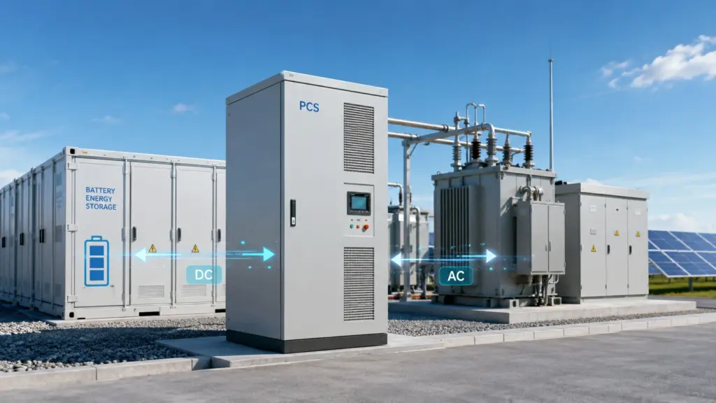
Main Functions of a Power Conversion System
A well-designed PCS performs several core functions in a battery energy storage system.
Bidirectional AC/DC Conversion
The PCS converts AC to DC for charging and DC to AC for discharging. This enables the battery to store electricity from the grid, solar system, generator or other AC source and release it when needed.
Active Power Control
Active power is the real usable power measured in kW or MW. The PCS controls how much power the battery charges or discharges at any moment.
This matters for peak shaving, load shifting, backup power and energy arbitrage.
Reactive Power and Power Factor Control
Reactive power helps manage voltage stability in AC systems. In commercial and grid-scale projects, the PCS may need to provide reactive power support, power factor correction or voltage regulation.
A system sized only for active power may fail to provide enough reactive power headroom. A 2026 industry case reported by ESS News showed that an undersized PCS and lack of reactive power margin caused a European BESS to underperform even though the batteries were healthy.
Voltage and Frequency Regulation
The PCS helps keep output voltage and frequency within required limits. In grid-connected mode, it synchronizes with the grid. In off-grid or microgrid operation, it may help establish or stabilize local voltage and frequency.
Grid Synchronization and Protection
For grid-tied systems, the PCS must synchronize with grid voltage, frequency and phase before exporting power. It also supports protection functions such as overvoltage, undervoltage, overcurrent, overtemperature, short-circuit protection, insulation monitoring and anti-islanding.
Monitoring and Diagnostics
Modern PCS units provide operating data such as power output, DC voltage, AC voltage, current, frequency, temperature, fault codes and operating mode. This data is essential for commissioning, troubleshooting, warranty evaluation and long-term O&M.
Grid-Forming Capability
Traditional grid-following PCS units follow an existing grid signal. Newer grid-forming PCS technology can help establish voltage and frequency in weak grids, microgrids or systems with high renewable penetration.
Main Components Inside a PCS
A PCS is usually built from several functional blocks.
1. Power Electronic Conversion Stage
This is the core of the PCS. It includes semiconductor switching devices such as IGBT, MOSFET or increasingly SiC-based power modules. These devices switch rapidly to shape electrical waveforms and control the direction and amount of power flow.
IGBT technology has been widely used in medium- and high-power applications. SiC devices are becoming more popular in advanced designs because they can support higher switching frequency, improved efficiency and higher power density, although cost and application requirements must be considered.
2. DC Side Interface
The DC side connects to the battery system. Important parameters include DC voltage range, maximum current, insulation design, DC breaker or contactor configuration, pre-charge circuit and protection coordination with the battery BMS.
For high-voltage battery systems, the PCS must match the battery voltage window across different states of charge. If the voltage range is mismatched, the usable battery capacity may be reduced or the system may frequently enter protection states.
3. AC Side Interface
The AC side connects to loads, switchgear, transformer or the utility grid. It must match the required AC voltage, frequency, phase configuration and grid code requirements. In commercial and utility projects, transformer selection and medium-voltage integration may also affect PCS design.
4. Filters and Power Quality Hardware
Filters reduce harmonics and improve waveform quality. In grid-connected systems, harmonic control, voltage stability and power factor are important for compliance and long-term equipment reliability.
5. Control Unit
The control unit is the “decision layer” of the PCS. It measures voltage, current, frequency, temperature and system status, then adjusts switching behavior in real time. It also handles active power control, reactive power control, grid synchronization, fault response and communication.
6. Protection Devices
A PCS normally includes multiple protection functions such as overvoltage, undervoltage, overcurrent, short-circuit, ground fault, overtemperature, anti-islanding and emergency shutdown. Protection coordination with BMS, EMS and site-level switchgear is essential.
7. Communication Interfaces
A PCS must communicate with the BMS, EMS, monitoring platform and sometimes grid dispatch systems. Common communication methods include CAN, RS485, Ethernet, Modbus TCP, Modbus RTU and other project-specific protocols.
Avepower battery systems commonly support communication integration for inverter and project matching. Installers can check related communication support through the Avepower inverter compatibility list.
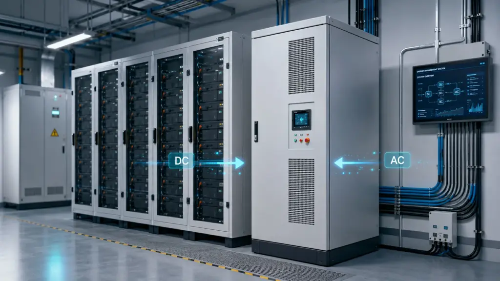
Main Types of PCS Used in Energy Storage
Different BESS projects require different PCS architectures. The right design depends on project size, DC voltage, AC voltage, redundancy needs, maintenance strategy and grid requirements.
1. Residential Hybrid PCS
In many home battery systems, PCS functions are integrated into a hybrid inverter. The system manages solar input, battery charging, battery discharging, backup output and grid interaction.
This type is common in systems below 10 kW and is suitable for residential solar self-consumption, backup power and small off-grid applications.
2. Commercial and Industrial PCS
C&I systems often use PCS units in the tens to hundreds of kilowatts. According to Infineon, C&I BESS commonly uses higher DC voltage platforms and three-phase AC output, with popular PCS sizes often ranging from 20 kW to 250 kW depending on system design.
This category is common for factories, hotels, farms, telecom rooms, EV charging support, warehouses and commercial buildings.
3. Modular PCS
A modular PCS uses multiple power modules connected in parallel. This improves redundancy and makes maintenance easier. If one module fails, the system may continue operating at reduced capacity.
Modular architecture is useful for projects that need phased expansion, easier serviceability or higher availability.
4. Centralized PCS
A centralized PCS is used in large C&I and utility-scale projects. It may serve many battery racks or containers through a shared DC bus.
Centralized PCS designs can reduce cost per kW and simplify large-scale integration, but they require careful protection design and redundancy planning.
5. String PCS
A string PCS assigns conversion hardware to smaller battery strings or battery clusters. This can improve fault isolation, battery-level flexibility and system availability.
String PCS design is increasingly attractive when battery cabinets are distributed or when the project requires better control over each battery branch.
6. High-Voltage and Utility-Scale PCS
Large BESS projects may use high-voltage PCS platforms connected to MV transformers and utility substations. For project developers planning larger systems, Avepower’s custom high-voltage battery storage system can be matched with project-specific voltage platforms, cabinet layouts and communication requirements.
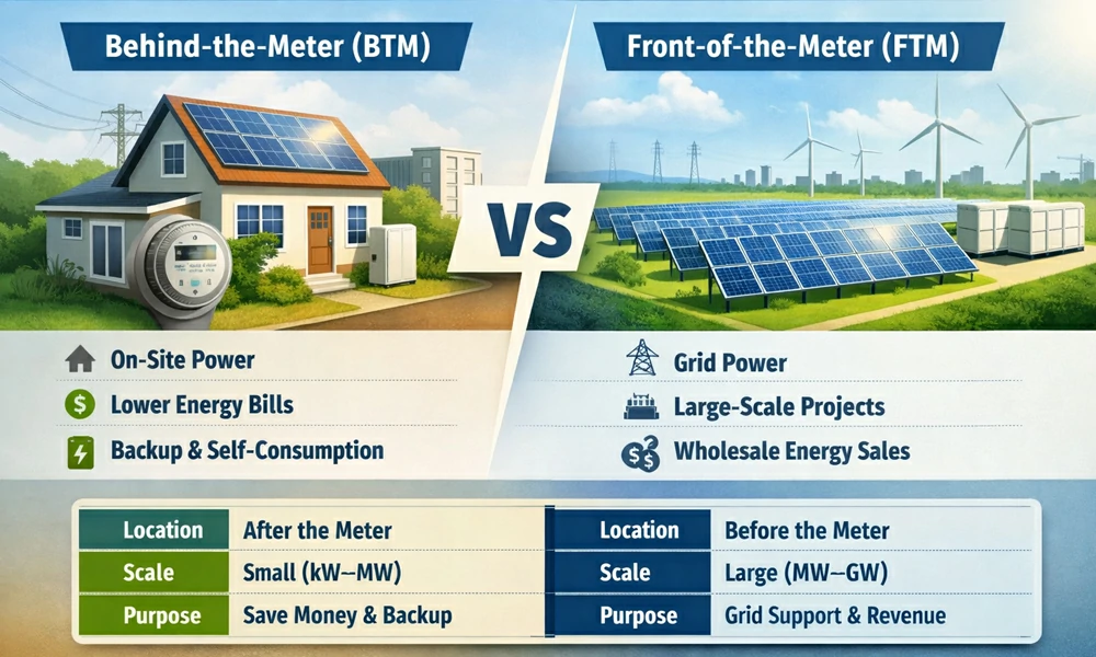
BTM vs FTM: Why PCS Design Changes by Application
A Power Conversion System should be selected based on how the storage system will operate.
Behind-the-Meter BESS
Behind-the-meter systems are installed on the customer side of the meter. Typical goals include:
- Solar self-consumption
- Backup power
- Demand charge reduction
- Time-of-use bill savings
- EV charging support
- Power quality improvement
Residential and small commercial BTM systems often prioritize safety, quiet operation, inverter compatibility, compact installation, monitoring and simple maintenance.
Avepower residential battery energy storage systems are typically designed around home solar storage, backup power, modular expansion and practical inverter matching.
Front-of-the-Meter BESS
Front-of-the-meter systems connect to the grid side and serve utility or market functions. Typical goals include:
- Frequency regulation
- Voltage support
- Renewable smoothing
- Energy arbitrage
- Capacity support
- Grid congestion relief
- Ancillary services
- Black start or grid-forming support
FTM projects require deeper grid studies, stricter grid code compliance, more advanced protection, higher PCS power ratings and often MV transformer integration.
How to Size a PCS for a Battery Energy Storage System
PCS sizing should consider both battery energy capacity and power demand.
Battery capacity is measured in kWh or MWh. PCS power is measured in kW or MW. These two values answer different questions.
- Battery capacity: How much energy can the system store?
- PCS power: How fast can that energy be charged or discharged?
A simple way to estimate discharge duration is:
Discharge duration = usable battery capacity ÷ PCS discharge power
For example:
| Battery Size | PCS Power | Approximate Full-Power Duration |
|---|---|---|
| 100 kWh | 50 kW | 2 hours |
| 200 kWh | 100 kW | 2 hours |
| 500 kWh | 250 kW | 2 hours |
| 500 kWh | 125 kW | 4 hours |
| 1 MWh | 500 kW | 2 hours |
However, real PCS sizing should also include:
- Peak load requirement
- Backup load priority
- PV generation profile
- Grid export limit
- Demand charge target
- Battery C-rate
- PCS overload ability
- Reactive power headroom
- Thermal derating
- Future expansion
- Local grid code requirements
For example, a 500 kWh battery paired with a 250 kW PCS may look like a two-hour system. But if the site also requires reactive power support, peak shaving during hot afternoons and continuous high output, the PCS may need additional headroom.
This is why Avepower recommends sharing the load profile, expected operating mode, grid voltage, inverter or PCS brand preference, backup duration and expansion plan before finalizing the battery configuration.
PCS, BMS and EMS: How They Work Together
A Power Conversion System should never be evaluated in isolation. In a battery energy storage system, it works with two other critical control layers: the BMS and EMS.
BMS: Battery Safety Layer
The Battery Management System monitors cell voltage, pack voltage, current, temperature, state of charge and safety limits. It protects the battery from overcharge, over-discharge, overcurrent, overheating, low-temperature charging and other abnormal conditions.
The BMS sends allowable charge and discharge limits to the PCS. If the battery is too hot, too cold, too full or too low, the BMS can reduce current limits or request shutdown.
PCS: Power Execution Layer
The PCS executes power commands. It physically controls how much power flows into or out of the battery and converts that power between DC and AC.
The PCS must obey both the EMS strategy and the BMS safety limits. For example, the EMS may request 100 kW discharge during peak demand, but if the BMS allows only 60 kW due to temperature or SOC conditions, the PCS should limit output accordingly.
EMS: Energy Strategy Layer
The Energy Management System decides when and why the battery should charge or discharge. It may optimize based on electricity price, solar generation, facility load, grid signals, backup reserve, demand charges or VPP dispatch requirements.
The EMS tells the PCS what the system should do. The BMS tells the PCS what the battery can safely do. The PCS converts those commands into real power flow.
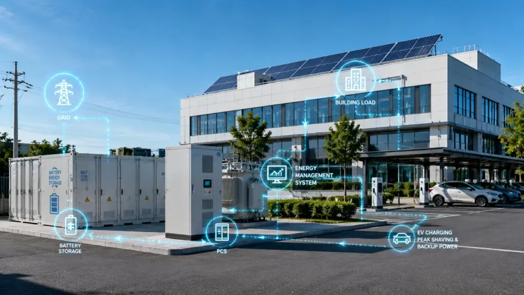
PCS Applications Across Different Energy Storage Projects
Residential Energy Storage
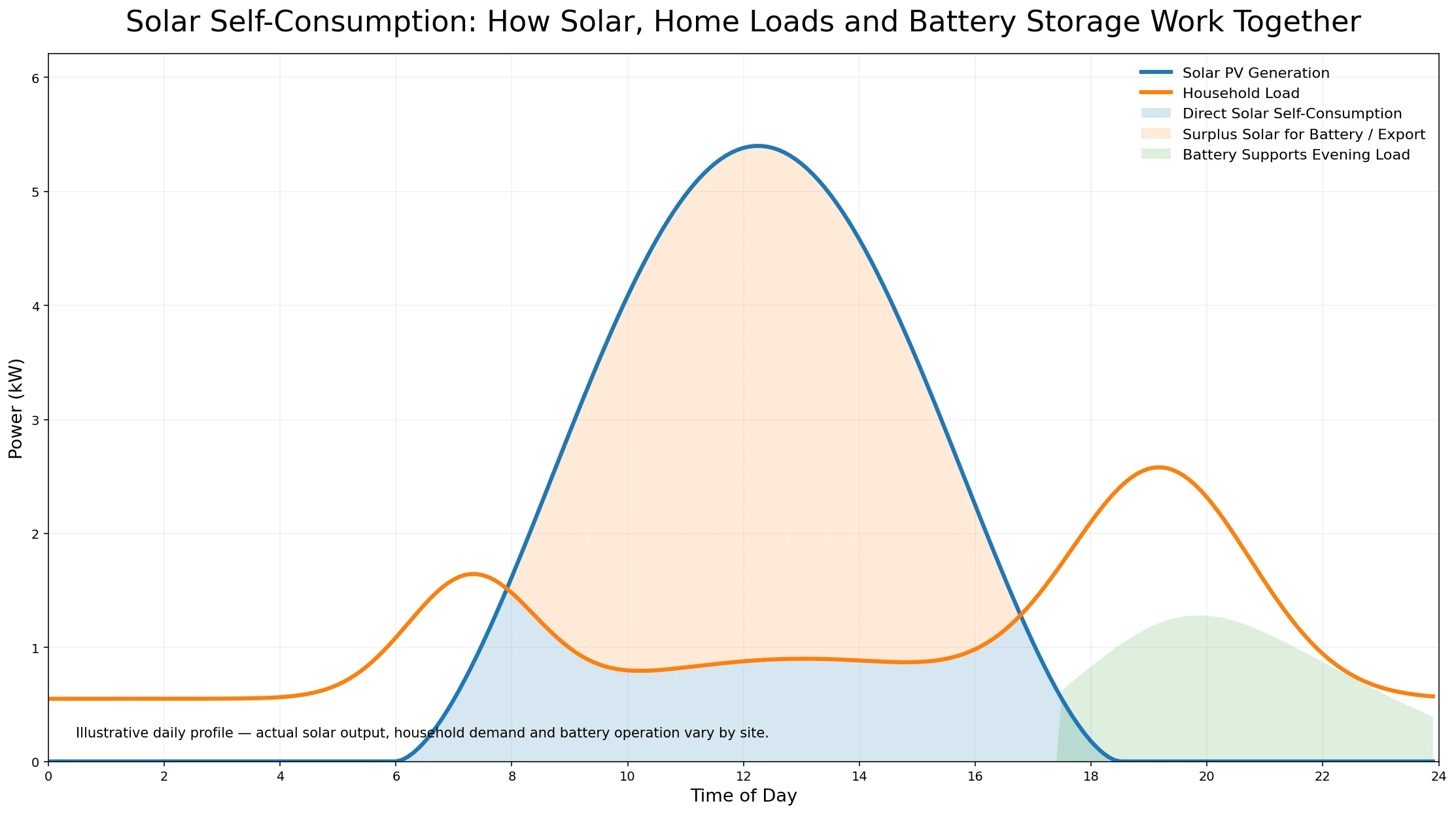
In home energy storage, PCS functions are often integrated into a hybrid inverter or all-in-one battery system. The system stores solar energy during the day and supplies power in the evening, during peak tariff periods or during outages.
Typical uses include:
- Solar self-consumption
- Essential-load backup
- Time-of-use optimization
- Off-grid cabins
- Small villas and farms
For residential projects, the key selection points are inverter compatibility, battery voltage, backup output, communication protocol, safety certification and installation simplicity. Avepower’s residential energy storage solution is designed for these types of applications.
Commercial and Industrial Energy Storage
In C&I systems, PCS selection becomes more technical. The system may need to manage high peak loads, support multiple battery cabinets, integrate with building load data and respond to tariff structures.
Typical uses include:
- Demand charge reduction
- Load shifting
- Factory backup power
- EV charging support
- Solar-plus-storage
- Power quality improvement
- Microgrid operation
For these applications, PCS sizing should be based on the load curve, peak demand, backup duration, battery C-rate, grid export limits and future expansion plan.
Utility-Scale Energy Storage
Utility-scale PCS platforms are designed for megawatt-level output, high DC voltage, complex grid requirements and long operating life. They may support grid-forming, reactive power control, frequency regulation, renewable smoothing and grid congestion relief.
This level of project requires detailed engineering studies, grid interconnection approval, protection coordination and long-term O&M planning.
Microgrids and Weak-Grid Regions
In weak-grid or off-grid regions, the PCS may need to do more than inject power. It may need to help stabilize the local grid, coordinate with diesel generators and maintain power quality under changing load conditions.
This is where grid-forming capability, overload design and EMS coordination become especially important.
Common PCS Selection Mistakes
Mistake 1: Choosing PCS Power Based Only on Battery Capacity
A 200 kWh battery does not automatically require a 200 kW PCS. The correct PCS depends on runtime, peak load, grid contract, battery C-rate and business case.
Mistake 2: Ignoring the Battery Voltage Window
The PCS must operate across the full DC voltage range of the battery system, not just the nominal voltage. Battery voltage changes with SOC, temperature and configuration.
Mistake 3: Forgetting Reactive Power
In commercial and grid-connected projects, reactive power can reduce available active power if the PCS is too close to its apparent power limit.
Mistake 4: Treating PCS and BMS Communication as Optional
Without proper BMS communication, the PCS may not receive real-time battery limits. This can cause unnecessary shutdowns, poor charging control or battery protection risks.
Mistake 5: Ignoring Thermal Derating
PCS output may drop in high ambient temperatures, poor ventilation or dusty environments. Cooling method and installation conditions should be checked early.
Mistake 6: Overlooking Grid Compliance
Different markets require different interconnection behavior. Before selecting a PCS, confirm anti-islanding, ride-through, power factor, voltage and frequency response requirements with the local grid operator.
Future Trends in Power Conversion Systems
PCS technology is evolving quickly because battery storage is moving from backup power into core grid infrastructure.
Grid-Forming PCS
Grid-forming technology is becoming more important as solar, wind and battery systems replace conventional synchronous generation. A grid-forming PCS can help support voltage and frequency rather than simply following the grid.
This is especially valuable for weak grids, islanded microgrids, remote industrial sites and renewable-heavy power systems.
Higher DC Voltage Platforms
Higher DC voltage can reduce current for the same power level, which can reduce cable size, losses and system complexity. Utility-scale systems are already moving toward high-voltage architectures, and some PCS platforms are designed for 1500 VDC or even higher future architectures.
SiC and Higher Power Density
Silicon carbide power devices can improve switching performance, reduce losses and increase power density. This may help PCS units become more compact and efficient, especially in high-power applications.
Modular and Serviceable Design
More projects now require lower downtime and easier O&M. Modular PCS design can improve serviceability and allow partial operation during maintenance.
Smarter EMS and Predictive Control
PCS data is becoming more valuable. With better monitoring, operators can detect temperature issues, abnormal power loss, communication errors, contactor problems and derating patterns before they become major failures.
Cybersecurity and Communication Standards
As BESS becomes more connected to grid systems and cloud platforms, PCS cybersecurity, firmware management and secure communication will become more important for bankable projects.
Avepower Practical Recommendation: Select Battery and PCS Together
For installers, distributors, EPCs and OEM/ODM buyers, the most important recommendation is to avoid treating the battery and PCS as separate purchasing decisions.
A safe and reliable energy storage project should define these items together:
- Battery chemistry and capacity
- Battery voltage platform
- BMS communication protocol
- PCS or inverter power rating
- AC output voltage and phase
- Grid-tied or off-grid operation
- Backup load requirement
- PV system configuration
- EMS control logic
- Installation environment
- Certification and documentation requirements
- Expansion plan
If your project involves solar-plus-storage, commercial backup power, peak shaving, off-grid operation or a high-voltage battery platform, it is better to confirm PCS matching before finalizing the battery configuration.
You can contact Avepower for project-specific guidance through the customized battery service or review available system categories from the main battery energy storage system manufacturer page.
Conclusion
A Power Conversion System is the power control center of a battery energy storage system. It converts DC and AC power, manages bidirectional energy flow, supports grid interaction, protects the battery system and translates EMS commands into real electrical output.
For simple solar applications, an inverter may be enough. But for serious energy storage projects, especially commercial, industrial, microgrid and utility-scale systems, PCS selection directly affects performance, safety, compliance and return on investment.
The best PCS is not always the largest or cheapest option. It is the one that matches the battery voltage platform, application profile, grid requirements, communication architecture, thermal environment and long-term operation strategy.
FAQ
A Power Conversion System PCS is the power electronics unit that converts electricity between DC and AC in a battery energy storage system. It charges the battery by converting AC to DC and discharges the battery by converting DC to AC for loads or the grid.
Not exactly. An inverter usually refers to DC-to-AC conversion. A PCS is broader because it normally supports bidirectional conversion, battery charge and discharge control, EMS/BMS communication, grid support, protection and monitoring.
A PCS manages the two-way flow of electricity in a battery energy storage system. It controls battery charging and discharging, supports stable power output, and helps the system operate safely and efficiently.
The main operating modes of a PCS are grid-tied mode, off-grid mode, and bidirectional operation. In grid-tied mode, the PCS works with the utility grid. In off-grid mode, it supplies local loads independently. In bidirectional operation, it supports both charging and discharging.
A PCS can provide overvoltage protection, overcurrent protection, frequency control, thermal monitoring, fault detection, and system shutdown functions to protect both the battery and connected equipment.
Bidirectional power conversion means the PCS can move electricity in both directions. It can convert AC to DC for charging and DC to AC for discharging depending on system demand.
A grid-forming PCS can help establish or stabilize voltage and frequency in weak grids, microgrids or islanded systems. It does not only follow the grid; it can help form the grid reference.
An undersized PCS may limit battery output, reduce revenue, fail to support reactive power, overheat, derate during high-load operation or fail to meet grid performance requirements.
The PCS executes power conversion and controls electrical output. The EMS decides the operating strategy, such as when to charge, discharge, export power or reserve energy for backup. In simple terms, the EMS gives commands and the PCS carries them out.
The BMS monitors and protects the battery cells and modules. The PCS converts and controls power between the battery and the AC system. The BMS protects the battery, while the PCS manages power conversion.
PCS size depends on the battery capacity, required discharge power, backup load, grid connection limit and application. For example, a 1 MWh battery with a 250 kW PCS is suitable for about 4 hours of full-power discharge, while a 500 kW PCS gives higher power for a shorter duration.
Common PCS communication protocols include CAN, RS485, Modbus TCP/IP, Ethernet and other project-specific interfaces. The correct protocol depends on the BMS, EMS and monitoring platform.