
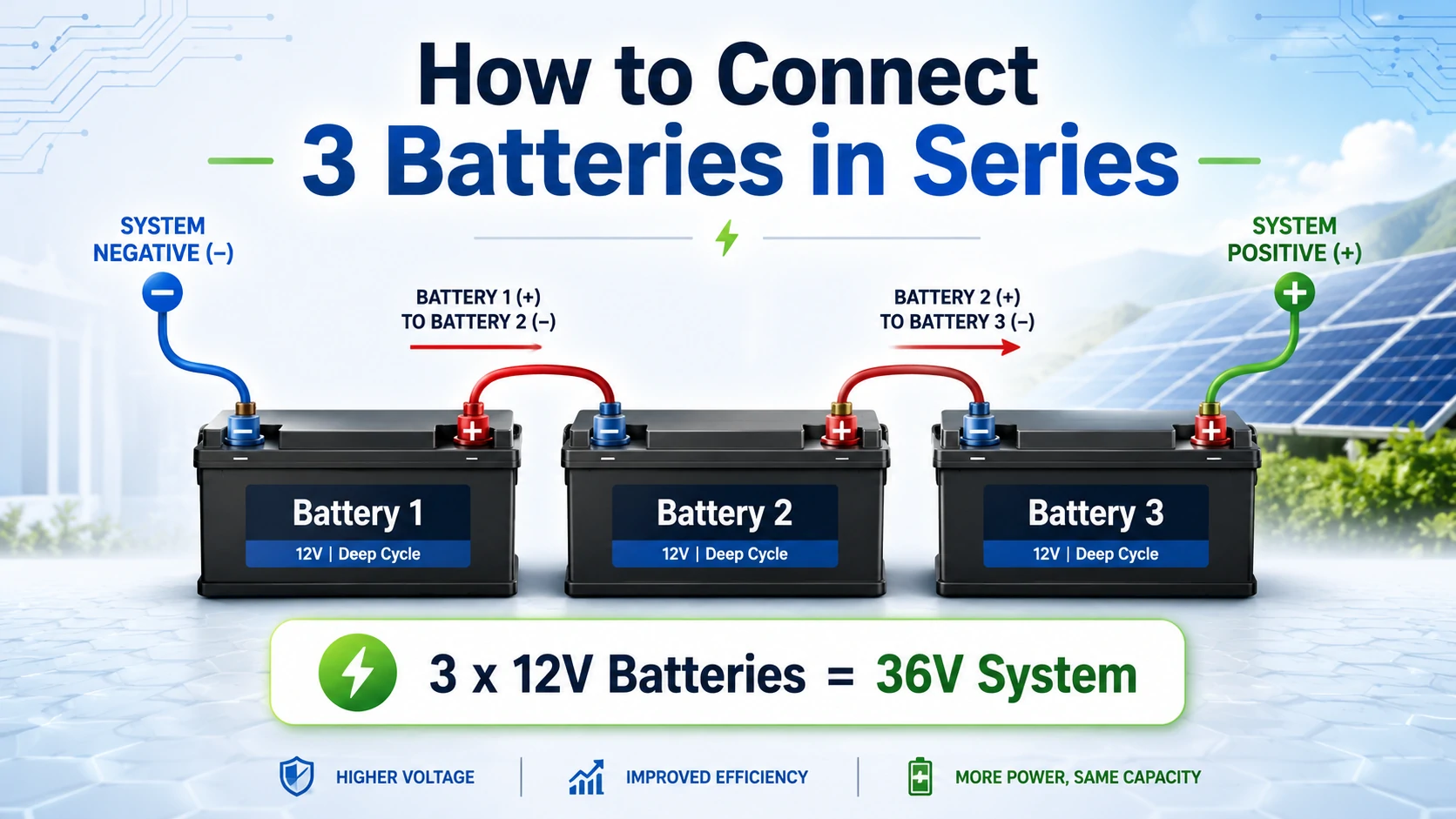
To connect three batteries in series, connect Battery 1 positive to Battery 2 negative, then connect Battery 2 positive to Battery 3 negative. The unused negative terminal on Battery 1 and unused positive terminal on Battery 3 become the main system terminals.
With three identical 12V 100Ah batteries, the finished bank is nominally 36V 100Ah, not 36V 300Ah. Voltage adds in series, while amp-hour capacity remains equal to one battery.
What Happens When You Connect Three Batteries in Series?
Connecting three batteries in series adds their voltages while the amp-hour rating remains unchanged. The same current flows through every battery, so the usable performance of the complete string is limited by the weakest battery, lowest BMS current limit, smallest cable and lowest-rated protection device.
Three-Battery Series Examples
| Battery Configuration | Nominal Bank Voltage | Bank Capacity | Nominal Energy |
|---|---|---|---|
| 3 × 12V 100Ah lead-acid | 36V | 100Ah | 3,600Wh |
| 3 × 12.8V 100Ah LiFePO4 | 38.4V | 100Ah | 3,840Wh |
| 3 × 6V 225Ah batteries | 18V | 225Ah | 4,050Wh |
| 3 × 24V 100Ah batteries | 72V | 100Ah | 7,200Wh |
The amp-hours do not triple in a series connection. However, total stored watt-hours increase because the bank contains the energy of all three batteries. This distinction between Ah and Wh is explained further in Avepower’s battery capacity guide and its comparison of batteries in series versus parallel.
Need a Safer Battery Configuration?
Not sure whether series wiring is suitable for your inverter or application? Avepower can help you evaluate battery voltage, capacity, BMS limits and communication compatibility before installation.
How Are Series and Parallel Connections Different?
Series wiring is used when equipment needs a higher operating voltage, while parallel wiring is used when the existing voltage is correct but more amp-hour capacity and runtime are required. Three batteries cannot simultaneously provide both increases unless additional batteries are used in a balanced series-parallel configuration.
| Feature | Three Batteries in Series | Three Batteries in Parallel |
|---|---|---|
| Terminal pattern | Positive to negative | Positive to positive and negative to negative |
| Total voltage | Adds together | Remains equal to one battery |
| Total Ah capacity | Remains equal to one battery | Adds together |
| Three 12V 100Ah result | 36V 100Ah | 12V 300Ah |
| Main purpose | Higher system voltage | Longer runtime |
| Current at equal power | Lower | Higher |
| Main design risk | One weak battery affects the string | Unequal current sharing |
| Typical applications | 36V motors, carts and equipment | 12V RV, marine and backup banks |
For a broader comparison, see Avepower’s guide to how to connect 3 batteries in parallel.
With only three identical 12V batteries, you can create either a 36V series string or a 12V parallel bank. You cannot build a balanced 24V series-parallel bank from three identical batteries. A balanced 3S2P configuration, for example, requires six batteries: two identical strings of three batteries.
Can Any Three Batteries Be Connected in Series?
No, three batteries should only be connected in series when they have matching voltage, chemistry, capacity, model, condition and charge level, and when the manufacturer explicitly permits the required series quantity. A matching label does not automatically mean the internal BMS or protection circuit supports a three-unit string.
Do Not Connect the Batteries in Series When
- The battery manual says “parallel only.”
- The maximum approved series quantity is less than three.
- One battery is older, weaker or from a different production batch.
- The batteries have different chemistries or capacities.
- One battery repeatedly reaches charge or discharge cutoff first.
- The charger, inverter, controller or motor is not rated for the total voltage.
- You intend to draw 12V from only one battery in the string.
- The cables, fuse or disconnect cannot safely handle the expected current and fault energy.
What Do You Need Before Wiring Three Batteries in Series?
A safe installation requires more than two jumper cables: you need compatible batteries, appropriately rated conductors, insulated tools, a DC-rated disconnect, overcurrent protection, terminal covers, a reliable multimeter and a charger designed for the completed battery bank. Every component must be rated for both system voltage and current.
Prepare the following equipment:
- Three identical, manufacturer-approved batteries
- Two battery-to-battery series jumper cables
- Main positive and negative system cables
- Correctly crimped cable lugs
- DC-rated fuse or circuit breaker
- DC-rated battery disconnect
- Digital multimeter with a suitable DC voltage range
- Insulated spanners or torque tools
- Terminal covers or insulating boots
- Eye protection and suitable gloves
- Charger matched to the final bank voltage and battery chemistry
- Manufacturer-specified terminal hardware
How Do You Connect 3 Batteries in Series Step by Step?
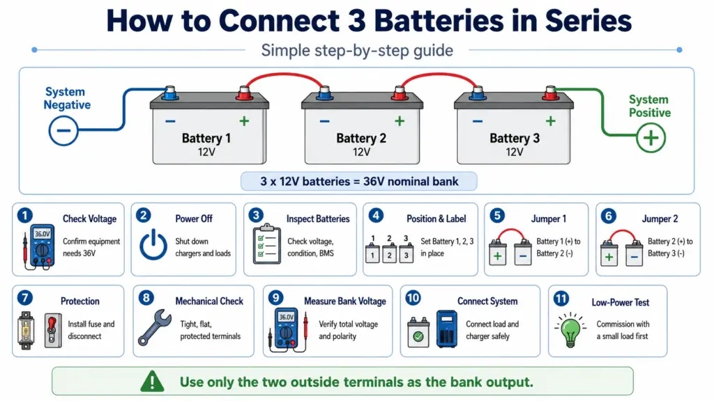
Shut down every charger and load, verify that all three batteries are compatible and similarly charged, connect the batteries positive-to-negative in a single chain, and use only the two remaining outside terminals as the bank output. Check polarity and total voltage before closing the disconnect or applying power.
Basic Three-Battery Series Diagram
System Negative
      |
      v
  [ Battery 1 ]
  (-)         (+)
               |
               | Series Jumper 1
               v
  (-)         (+)
  [ Battery 2 ]
               |
               | Series Jumper 2
               v
  (-)         (+)
  [ Battery 3 ]
                |
                v
         System Positive
The actual electrical path is:
System (-) → Battery 1 → Battery 2 → Battery 3 → System (+)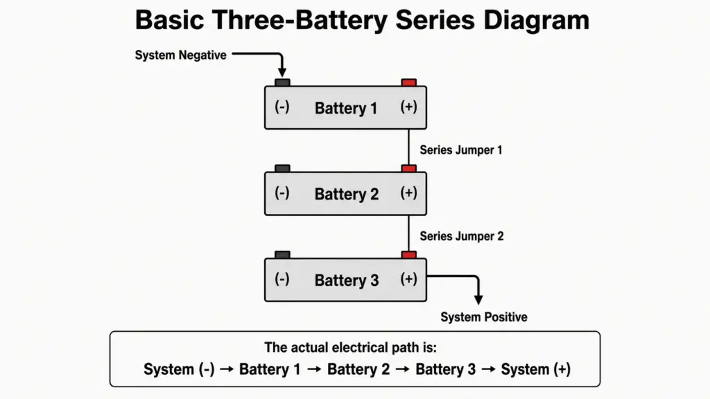
Step 1: Confirm the Required System Voltage
Check the voltage label and manual for the inverter, motor, controller, charger or DC load.
Three 12V batteries produce a 36V nominal bank. Do not connect that bank to equipment designed for 12V or 24V.
Step 2: Shut Down and Isolate All Energy Sources
Turn off and disconnect:
- AC chargers
- Solar charge controllers
- Inverters
- Alternators or DC-to-DC chargers
- Motors
- DC loads
- Automatic transfer or charging devices
Open the battery disconnect and confirm with a meter that no external charging voltage is present.
Never install series jumpers while a charger or load remains connected.
Step 3: Inspect and Measure Every Battery
Check each battery for physical damage, corrosion, loose terminals or abnormal temperature.
Measure and record the open-circuit voltage of all three batteries. The batteries should be brought to the manufacturer’s required state-of-charge range before connection.
For lithium batteries, do not rely only on a displayed SOC percentage. Confirm actual terminal voltage, BMS status and any active alarms.
Step 4: Position and Label the Batteries
Place the batteries on a secure, nonconductive and appropriately ventilated mounting surface.
Label them:
- Battery 1
- Battery 2
- Battery 3
Arrange the terminals so the jumper cables can remain short and protected without being sharply bent or placed under mechanical tension.
Step 5: Connect Battery 1 Positive to Battery 2 Negative
Install the first series jumper between:
- Battery 1 positive terminal
- Battery 2 negative terminal
Use the correct terminal hardware and tighten it to the battery manufacturer’s specified torque.
Do not place a tool across both terminals or between a positive terminal and a grounded metal surface.
Step 6: Connect Battery 2 Positive to Battery 3 Negative
Install the second jumper between:
- Battery 2 positive terminal
- Battery 3 negative terminal
At this stage, the three batteries form one electrical string.
The two free terminals should now be:
- Battery 1 negative: system negative
- Battery 3 positive: system positive
The orientation may be physically reversed, but the electrical rule remains the same: only the two terminals at opposite ends of the string become the system output.
Step 7: Install the Main Protection and Disconnect
Install the DC-rated overcurrent protection and disconnect in the locations required by the equipment manual and local rules.
A common design places the main fuse or breaker close to the bank’s positive output so that the downstream positive conductor is protected. However, the final protection architecture must be based on:
- Battery fault-current capability
- Cable ampacity
- Inverter or motor requirements
- Fuse interrupt rating
- Manufacturer instructions
- Local installation requirements
Do not use an AC-only circuit breaker in a DC battery circuit unless it is specifically rated for the DC voltage and available fault current.
Step 8: Check the Connections Mechanically
Verify that:
- Every cable lug sits flat against the terminal
- No washer interrupts the main electrical contact
- Terminal hardware is tightened to specification
- Cables cannot rub against sharp edges
- Positive terminals are covered
- No cable is pulling sideways on a terminal
- Tools and loose metal objects have been removed
Loose connections create resistance, heat and voltage drop even when the cable itself is correctly sized.
Step 9: Measure the Total Bank Voltage
Set the multimeter to the correct DC voltage range.
Place the black probe on Battery 1 negative and the red probe on Battery 3 positive.
For three 12V batteries, the reading should be approximately 36V nominal. The actual value depends on battery chemistry and state of charge.
For three charged 12.8V LiFePO4 batteries, a reading in the high-30V to low-40V range may be normal. Dakota Lithium, for example, gives approximately 38–42V as a quick-check range for a charged 36V-class LiFePO4 setup.
If the meter shows:
- Approximately 12V: one or more jumpers are missing or incorrectly positioned.
- Approximately 24V: only two batteries are contributing.
- Negative voltage: the meter probes or system polarity are reversed.
- Near zero: there may be a wrong connection, open BMS or battery fault.
- Unexpectedly high voltage: stop and check the battery ratings and meter setting.
Step 10: Connect the Load and Charger With the Disconnect Open
Connect the main positive and negative cables only after the completed bank has passed the voltage and polarity checks.
Keep the battery disconnect open while making the final system connections.
Before closing it, verify:
- Load voltage range
- Charger output voltage
- Positive and negative polarity
- Fuse and breaker ratings
- Communication or BMS requirements
- Emergency shutdown method
Step 11: Commission the System at Low Power
Close the disconnect and begin with a small controlled load.
Monitor:
- Total bank voltage
- Individual battery voltages
- Cable and terminal temperature
- BMS alarms
- Current
- Unexpected voltage drop
- Charger behavior
Do not apply the maximum inverter or motor load until the bank operates normally at low power.
What Voltage and Capacity Do Three 12V 100Ah Batteries Produce?
Three 12V 100Ah batteries connected in series produce a nominal 36V 100Ah battery bank with 3,600Wh, or 3.6kWh, of nominal energy. Three 12.8V 100Ah LiFePO4 batteries produce 38.4V 100Ah and 3,840Wh, although actual usable energy depends on discharge limits and conversion efficiency.
Lead-Acid Calculation
Three batteries:
3 × 12V = 36V
Capacity:
100Ah
Energy:
36V × 100Ah = 3,600Wh
Final nominal bank:
36V 100Ah, 3.6kWh
LiFePO4 Calculation
Three 12.8V batteries:
3 × 12.8V = 38.4V
Capacity:
100Ah
Energy:
38.4V × 100Ah = 3,840Wh
Final nominal bank:
38.4V 100Ah, 3.84kWh
Why the Higher Voltage Reduces Current
Suppose a load requires 1,800W.
At 12V, ignoring conversion losses:
1,800W ÷ 12V = 150A
At 36V:
1,800W ÷ 36V = 50A
The 36V system carries one-third of the current for the same power.
Because conductor heating is approximately proportional to current squared, expressed as I²R, reducing current to one-third can reduce resistive cable loss to roughly one-ninth when cable resistance is unchanged.
Real systems also have inverter, cable and connection losses, so actual current will be higher than the ideal calculation.
How Long Will a 36V 100Ah Series Bank Run?
Runtime depends on usable battery energy rather than amp-hours alone, so you must account for total watt-hours, permitted depth of discharge, inverter efficiency, temperature and actual load. A nominal 3.84kWh lithium bank will not necessarily provide the full 3.84kWh to an AC appliance.
Use this formula:
Runtime = Nominal energy × usable DoD × system efficiency ÷ load
Example assumptions:
- Battery bank: 38.4V 100Ah
- Nominal energy: 3.84kWh
- Usable depth of discharge: 80%
- Inverter and wiring efficiency: 90%
- Average AC load: 1.2kW
Calculation:
3.84kWh × 0.80 × 0.90 = 2.7648kWh usable AC energy
2.7648kWh ÷ 1.2kW = approximately 2.3 hours
Avoid the Risks of Multiple 12V Batteries in Series
A purpose-built 24V, 48V or 51.2V LiFePO4 battery can simplify wiring, improve BMS coordination and provide more reliable inverter communication. Explore a battery platform designed around your project requirements.
How Should You Charge Three Batteries in Series?
Charge the completed bank with a charger designed for the total series voltage and the correct battery chemistry, or use a properly isolated multi-bank charger that charges each battery independently. A standard 12V charger must never be connected across the two outside terminals of a 36V battery bank.
There are three common charging methods.
Method 1: Charge the Complete Series Bank
Use a charger designed for the total system voltage.
Examples:
- Three 12V lead-acid batteries: approved 36V lead-acid charger
- Three 12.8V LiFePO4 batteries: manufacturer-approved 36V-class lithium charger
- Three 24V batteries: approved 72V charger
The charger must match:
- Battery chemistry
- Required absorption or constant-voltage level
- Maximum charging current
- Temperature limits
- BMS operating requirements
- Total series voltage
Do not select a charger only because its label says “36V.” Different chemistries and products can have different charging profiles.
Method 2: Use an Isolated Three-Bank Charger
A multi-bank charger can charge each 12V battery individually while the batteries remain wired in series, but only when each charging output is electrically isolated and the charger manufacturer approves that configuration.
This method is common in marine and trolling motor systems. Minn Kota states that series-connected batteries can be charged individually using an appropriate multi-bank onboard charger.
Do not assume that three ordinary non-isolated 12V charger outputs can be used this way.
Method 3: Disconnect and Charge Each Battery Separately
Individual charging can help restore balance or diagnose a weak battery.
Before doing this:
- Shut down all loads and charging sources.
- Open the disconnect.
- Confirm the circuit is de-energized.
- Remove the required series connections safely.
- Charge each battery using the correct single-battery profile.
- Recheck voltage and condition before rebuilding the string.
This method requires more labor but allows each battery to be evaluated independently.
How Do You Check Whether the Series Bank Is Balanced?
Measure both total bank voltage and individual battery voltage during charging and discharging, because a normal total reading can conceal one overcharged or deeply discharged battery. A growing voltage difference, repeated BMS cutoff or one battery reaching its limit first indicates imbalance or unequal battery condition.
A basic inspection should include:
- Measure each battery at rest.
- Record total bank voltage.
- Apply a controlled load.
- Measure each battery again under the same current.
- Charge the bank and monitor each battery near the upper charge range.
- Compare temperatures and BMS data where available.
Stop and investigate when:
- One battery voltage falls much faster under load
- One battery reaches charge cutoff first
- One BMS disconnects before the others
- A battery becomes warmer than the rest
- Total voltage repeatedly collapses under moderate load
- The voltage difference increases over successive cycles
- One battery cannot reach the same state of charge
There is no universal acceptable voltage difference for every chemistry and model. Use the battery manufacturer’s limits rather than applying one generic threshold.
Is Three 12V Batteries or One 36V Battery Better?
Three 12V batteries offer flexible sourcing and individual replacement, but one purpose-built 36V battery usually provides fewer connections, centralized monitoring and better internal cell management. For lithium systems, an integrated 36V pack is often the cleaner choice unless the 12V batteries are explicitly designed for series operation.
Replacing one battery in an aged series string is not always advisable. A new battery may have a different capacity and internal resistance from the remaining batteries. Test the complete string and follow the manufacturer’s replacement policy.
Avepower already provides information specifically covering three 12V batteries in a 36V golf cart and four 12V batteries in series for a 48V system. These guides can help buyers compare modular strings with purpose-built higher-voltage battery packs.
Build a Battery System for Your Next Project
Avepower supports solar installers, distributors and OEM/ODM partners with customizable battery capacity, enclosure design, BMS protocols and inverter compatibility. Share your voltage, power and application requirements to receive a suitable solution.
Calculation Example: Three 12V 100Ah LiFePO4 Batteries
A three-battery LiFePO4 system can power a 36V-class load when every battery permits series operation and the load accepts the complete voltage range. The calculation should include nominal energy, maximum charging voltage, DC current, BMS current limits, usable depth of discharge and conversion losses.
Assume:
- Three 12.8V 100Ah LiFePO4 batteries
- Each battery permits at least three in series
- Each battery specifies 14.4V charging
- 1,800W AC load
- 90% inverter efficiency
- 80% planned usable energy window
Bank Voltage
12.8V × 3 = 38.4V nominalMaximum Charging Voltage
14.4V × 3 = 43.2VThe inverter and every DC protection device must tolerate at least this operating voltage, with any additional design margin required by the equipment manufacturer or applicable standard.
Bank Capacity
100AhThe Ah rating remains the same because the batteries are connected in series.
Nominal Energy
38.4V × 100Ah = 3,840WhApproximate DC Current at a 1,800W AC Load
DC current = AC power ÷ (Battery voltage × Inverter efficiency)

DC current = 1,800W ÷ (38.4V × 0.90)

DC current ≈ 52A
Each battery, BMS, jumper cable, terminal and protection device must continuously carry approximately 52A at nominal voltage. Start-up loads may require substantially more current, so inverter surge power must also be checked.
Approximate Usable AC Energy
3.84kWh × 80% usable energy × 90% inverter efficiency
= 2.76kWh
Approximate Runtime
2.76kWh ÷ 1.8kW = 1.53 hoursThis is a planning estimate rather than a guaranteed runtime. Temperature, cable loss, battery age, BMS limits, inverter standby consumption and load surges can reduce the actual result.
When Is a Purpose-Built 36V, 48V or 51.2V Battery Better?
A purpose-built higher-voltage battery is usually the better option for permanent solar storage, high-power backup and professional installations. It reduces external jumpers, coordinates cell monitoring through one BMS and may provide direct CAN or RS485 communication with the inverter.
Building a higher-voltage bank from separate 12V batteries may be reasonable for compatible trolling motors, mobile equipment, temporary systems and manufacturer-approved replacement applications. It becomes less attractive when the project requires:
- Closed-loop inverter communication
- Individual cell monitoring
- High continuous power
- Remote diagnostics
- Installer warranty support
- Fewer external terminals
- Coordinated charge and discharge limits
- Parallel capacity expansion
- Long-term stationary operation
Avepower provides purpose-built low-voltage lithium battery solutions across 24V, 48V and 51.2V-class platforms. Many are designed for parallel expansion and provide CAN, RS485 or RS232 communication rather than relying on separate 12V batteries connected in series.
For example, a 51.2V 280Ah battery stores:
51.2V × 280Ah = 14,336WhThat is approximately 14.3kWh in a single coordinated voltage platform, reducing the number of external series connections compared with assembling a similar system from multiple small batteries.
Communication does not correct an electrical voltage mismatch. The battery voltage range, inverter DC input range and supported BMS protocol must all be verified independently, as explained in Avepower’s battery communication guide.
Build a Safer Battery System With Avepower
Avepower supports installers, distributors, EPCs and OEM buyers with LiFePO4 battery selection, custom voltage design, BMS configuration, inverter compatibility and technical documentation.
Whether your project needs an approved 36V battery, a 48V home storage platform or a custom higher-voltage battery system, Avepower can evaluate the required capacity, operating current, communication protocol and installation environment before production.
Start a custom battery project or contact Avepower to request a project-matched battery solution.
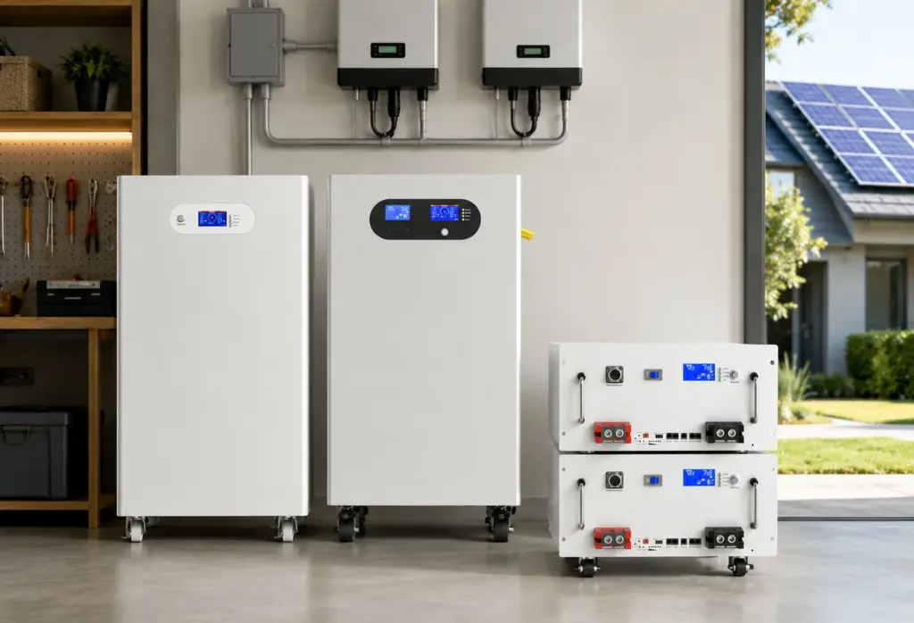
Take Control of Your Energy with Avepower!
Reliable home solar battery solutions with OEM/ODM customization and in-house manufacturing, tailored to the needs of distributors, installers, and energy partners.
FAQ
Three matching 12V batteries connected positive-to-negative produce a nominal 36V battery bank. The batteries, BMS, charger and load must all support the configuration.
Connect Battery 1 positive to Battery 2 negative. Connect Battery 2 positive to Battery 3 negative. Use Battery 1 negative as the main negative and Battery 3 positive as the main positive.
The completed bank remains 100Ah. The voltage increases, but amp-hour capacity does not. Three 12V 100Ah batteries produce 36V 100Ah and 3,600Wh nominal energy.
Not at the same voltage and load conditions. Series wiring adds voltage and total watt-hours, but Ah remains unchanged. Runtime must be calculated from watt-hours, usable depth of discharge, efficiency and actual load power.
Not by connecting one ordinary 12V charger across the complete bank. Use an approved 36V charger, an isolated multi-bank charger or safely disconnect and charge each battery individually.
Adding another identical 12V battery would raise the nominal system from 36V to 48V. Do this only if the battery manufacturer permits four in series and every charger, load, breaker and controller is rated for 48V operation.
The main cables connect to the two free outside terminals. In the diagram used here, Battery 1 negative is the system negative and Battery 3 positive is the system positive.