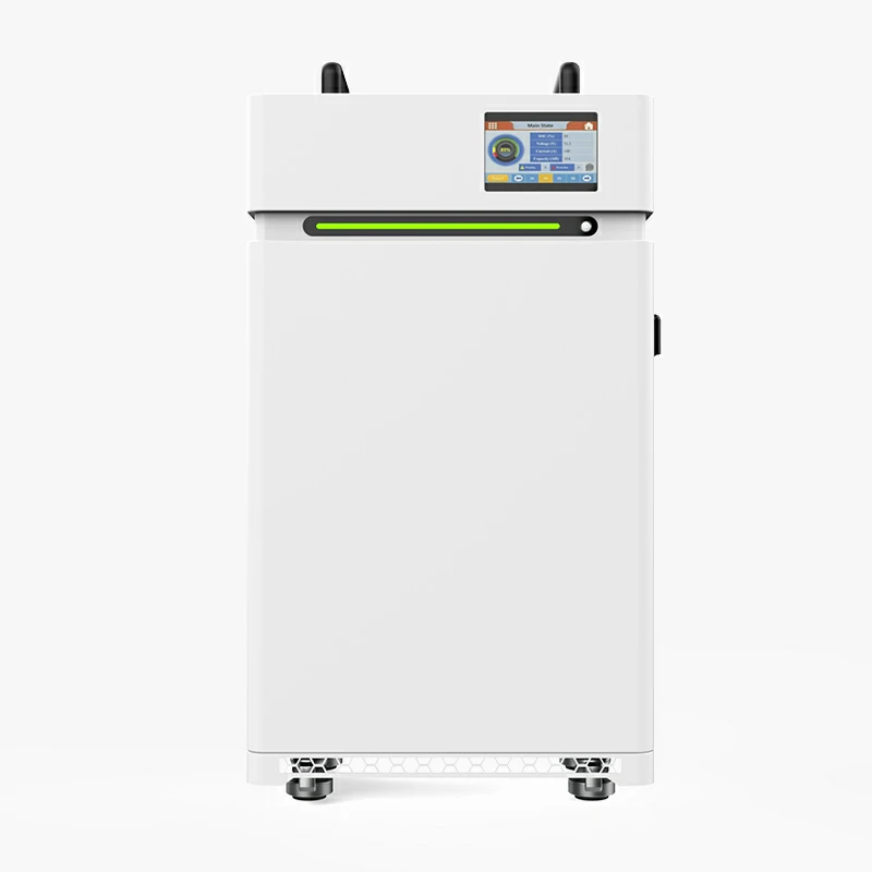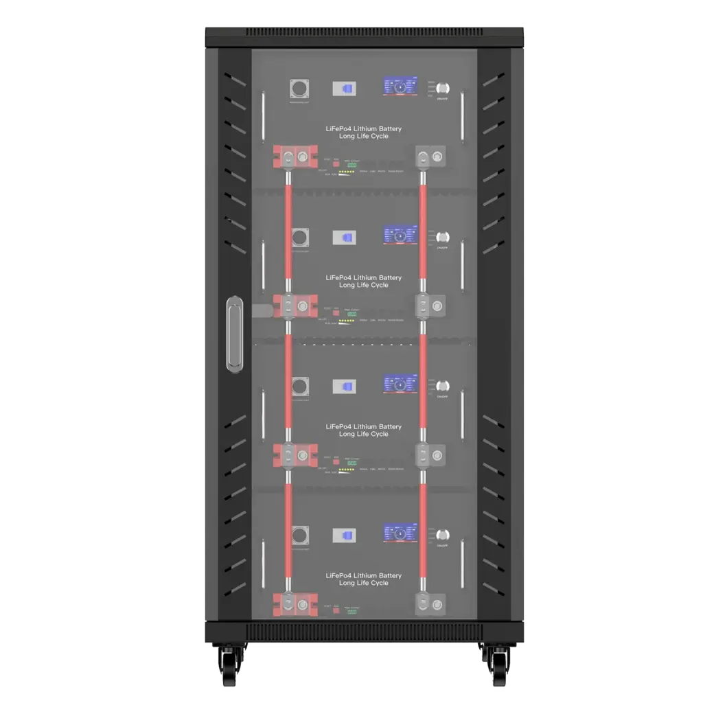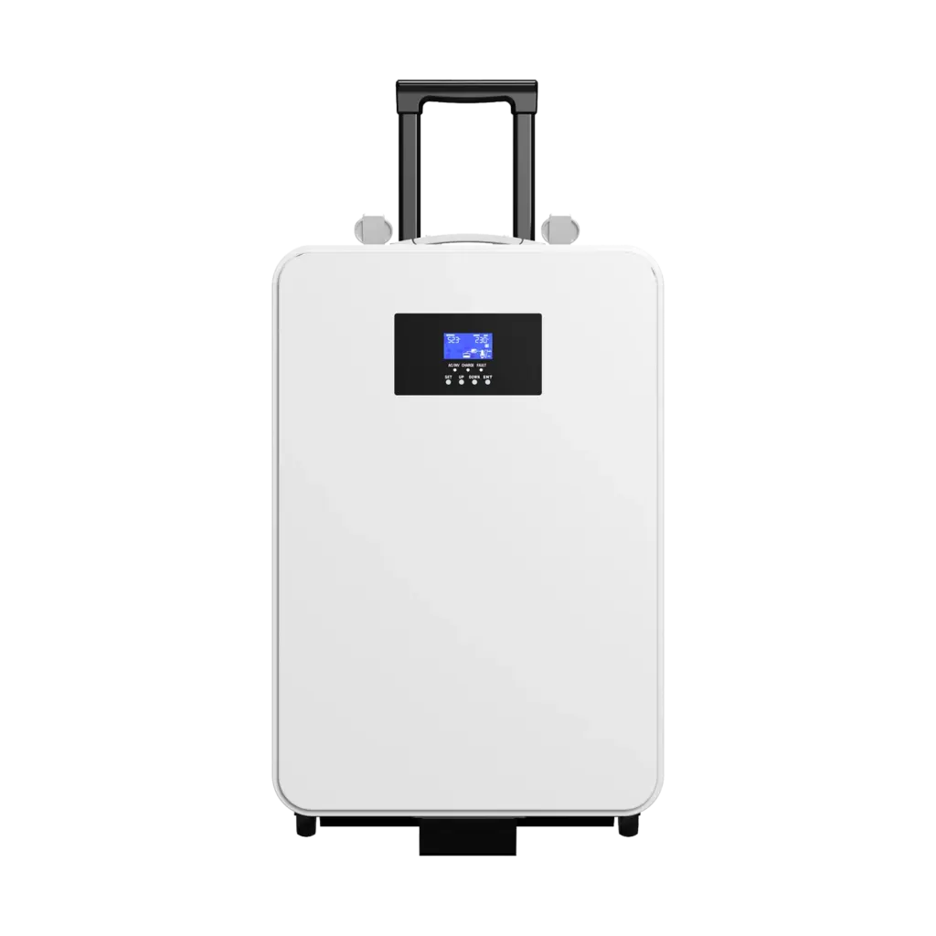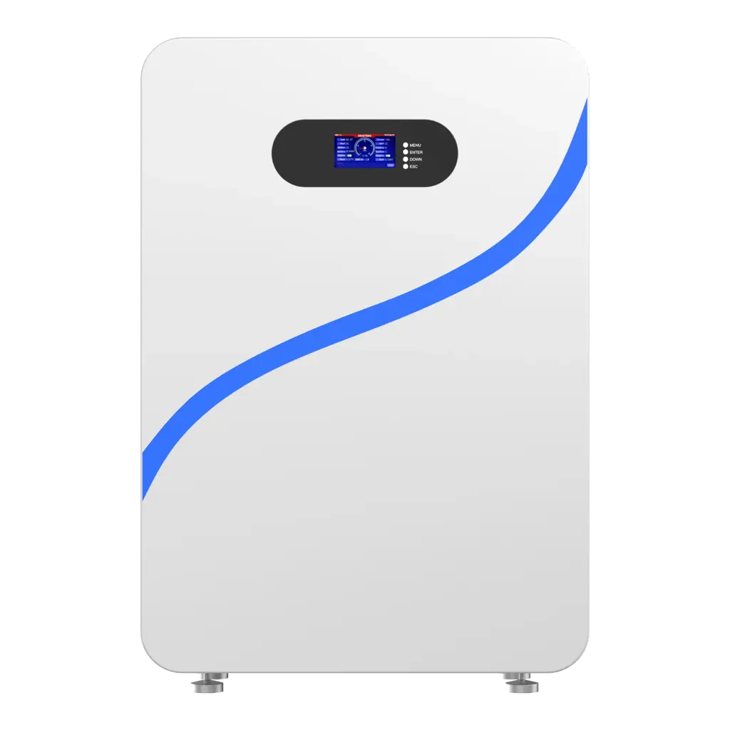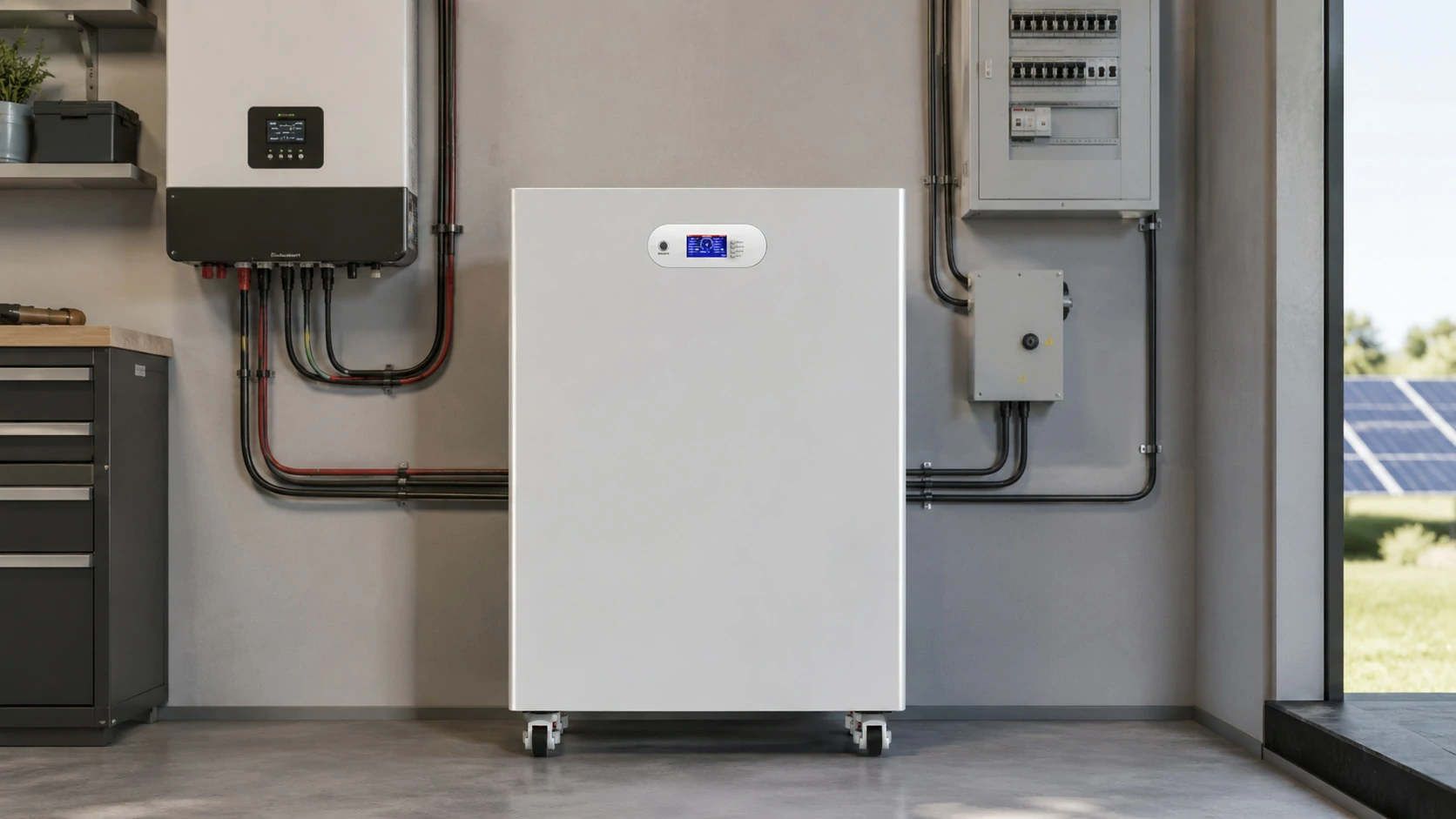

Battery storage design should begin with the load profile and operating objective—not with a preferred battery model. A reliable design matches battery energy, PCS power, voltage, controls, thermal management, protection and site conditions while accounting for efficiency losses, auxiliary consumption, degradation and applicable installation standards.
This guide explains how to develop a defensible battery energy storage system design for residential, commercial and industrial projects. It also shows where simplified sizing methods work—and where a detailed engineering study is required.
What Is Battery Storage Design?
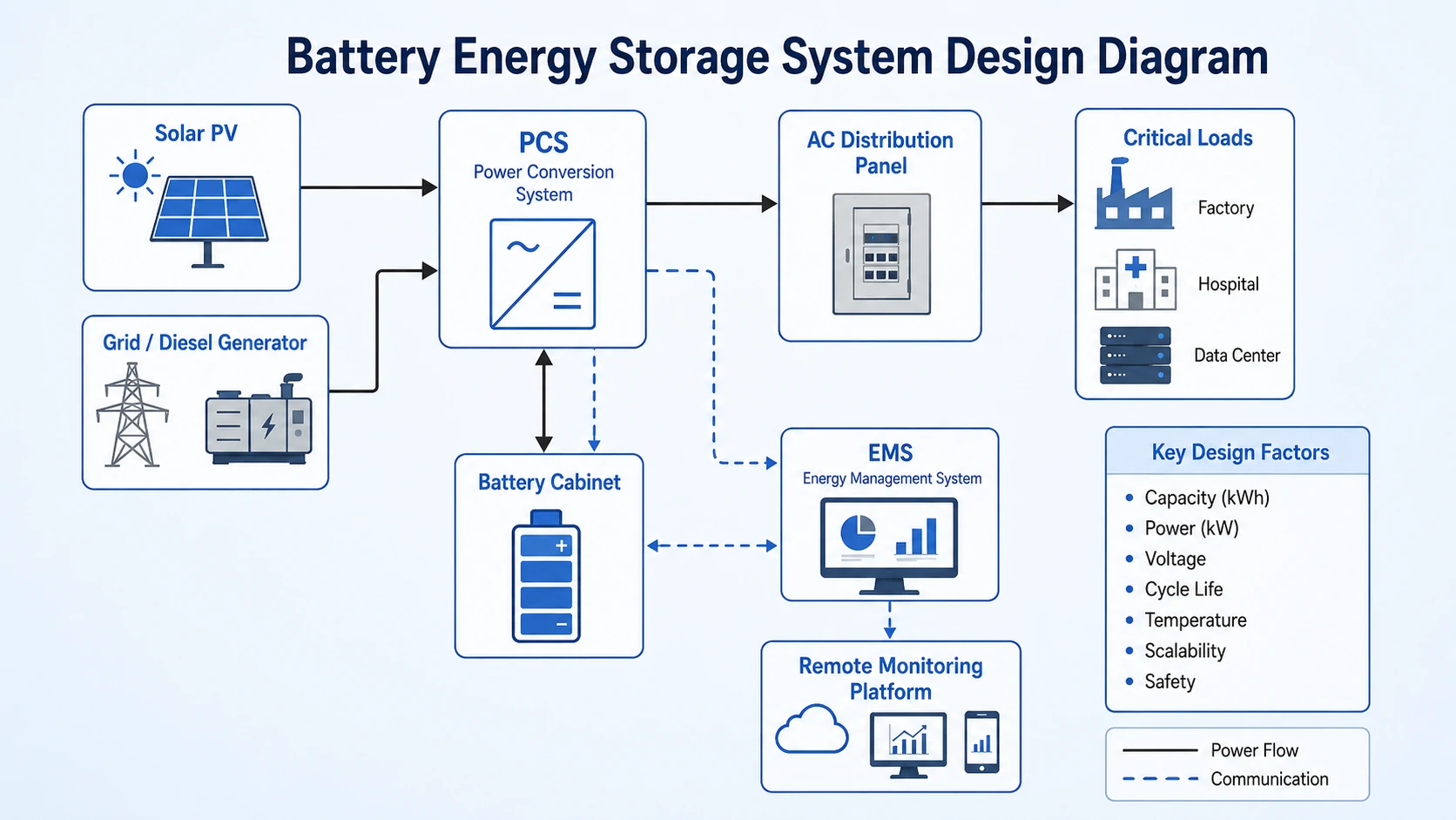
Battery storage design defines how a complete energy storage system will store, convert, control and safely deliver electricity. It covers the battery cells, modules, BMS, inverter or PCS, EMS, protection equipment, communications, enclosure, thermal management, site layout and connection to the building, solar system or grid.
A Battery Energy Storage System, or BESS, is not simply a group of battery cells. It is an integrated electrical system in which every component must remain inside the approved voltage, current, temperature and communication limits.
What Information Is Needed Before Designing a Battery Storage System?
A battery storage project should begin with measured load, generation, tariff, outage and site data rather than a preferred battery model. The minimum inputs are the project objective, interval load profile, required backup duration, peak power, available charging energy, electrical connection, installation environment and applicable regulatory requirements.

Planning a Battery Storage Project?
Share your required capacity, power, application and inverter model. Avepower can help you evaluate the right battery architecture before you finalize the system design.
How Do You Calculate Battery Power and Energy Capacity?
Battery power should be sized from the highest simultaneous discharge or charge requirement, while battery energy should be sized from the load multiplied by operating duration and adjusted for auxiliary loads, usable depth of discharge, conversion efficiency, design margin and end-of-life capacity retention.
Power and energy must be calculated separately.
- Power, measured in kW, determines how much load the system can support at one moment.
- Energy, measured in kWh, determines how long that power can be sustained.
- Duration, measured in hours, is approximately usable energy divided by delivered power.
The simplest energy calculation is:
Required delivered energy = Load × Operating time
That calculation is only a starting point. A more realistic design equation is:
Nominal battery energy = Required delivered energy ÷
(Usable DoD × Discharge-path efficiency × End-of-life capacity factor)
Where:
- Usable DoD is the permitted operating depth of discharge;
- Discharge-path efficiency includes battery and PCS losses during discharge;
- End-of-life capacity factor represents the minimum retained capacity used in the design;
- Auxiliary loads and design margin should be included before applying these factors.
Worked Battery Storage Sizing Example
A commercial facility wants to reduce grid demand by 100 kW for 1.5 hours.
Assume:
- Peak-shaving target: 100 kW;
- Battery-system auxiliary load: 3 kW;
- Operating duration: 1.5 hours;
- Forecast and design margin: 10%;
- Usable depth of discharge: 90%;
- One-way discharge efficiency: 94%;
- End-of-life retained capacity used for design: 80%.
First calculate the required delivered energy:
(100 kW + 3 kW) × 1.5 hours × 1.10 = 169.95 kWh
Beginning-of-life nominal capacity:
169.95 ÷ (0.90 × 0.94) = 200.9 kWh
Capacity required to deliver the same service at the assumed end-of-life condition:
169.95 ÷ (0.90 × 0.94 × 0.80) = 251.1 kWh
The example shows why a “100 kW for 1.5 hours” requirement does not automatically equal a 150 kWh battery. A design based only on load multiplied by duration could be undersized by more than 100 kWh under the stated assumptions.
These assumptions are illustrative rather than universal. Final calculations should use the selected battery’s guaranteed capacity, temperature derating, discharge curve, PCS efficiency map, state-of-charge limits and warranty conditions.
Do Not Use Round-Trip Efficiency for Every Calculation
Round-trip efficiency is useful when estimating how much purchased or solar energy is lost over a complete charge-and-discharge cycle. Backup-runtime calculations, however, should normally use the efficiency of the discharge path rather than applying full round-trip efficiency to energy that is already stored.
Need Help Sizing Your BESS?
Avoid oversizing the battery or undersizing the PCS. Send us your load profile, backup duration and solar generation data for a project-based battery storage recommendation.
How Should PCS Power Be Sized?
The PCS should support the maximum expected active power while also satisfying reactive-power, overload, motor-starting, grid-code and charging requirements. Matching the PCS only to average load can cause overload trips even when the battery contains enough stored energy.
A preliminary PCS rating can be expressed as:
PCS active-power rating ≥ Maximum simultaneous supported load + system margin
For the previous 100 kW example, a 100 kW PCS may appear adequate. A 110–125 kW class PCS may be more appropriate when auxiliary loads, reactive power, temperature derating or short-duration load variation are significant. The correct value must come from the actual load and network study.
The Avepower inverter size chart provides additional guidance for matching battery capacity, inverter output and load requirements.
What Components Must Be Matched in a BESS Design?
Every electrical and control component must operate across the battery’s full voltage, current and temperature range. Matching only nominal voltage is insufficient because battery voltage changes with state of charge, temperature, load and protection status.
| Component | Critical Checks |
|---|---|
| Battery cells and modules | Chemistry, voltage range, capacity, C-rate, temperature, cycle and calendar life |
| BMS/BMU/BCU | Voltage and temperature sampling, balancing, limits, alarms and contactor control |
| PCS or inverter | DC voltage window, continuous power, surge, efficiency, grid code and control modes |
| DC protection | Fault current, interrupt rating, polarity, isolation and coordination |
| AC protection | Voltage, current, fault level, anti-islanding and interconnection requirements |
| Transformer | kVA, voltage ratio, impedance, losses, harmonics and cooling |
| EMS | Dispatch logic, reserve SOC, tariff control, peak limit and remote commands |
| Communications | Interface, protocol, pinout, baud rate, addressing, firmware and fail-safe behavior |
| Thermal system | Heat load, ambient range, airflow or liquid cooling and auxiliary power |
| Enclosure | IP/NEMA rating, corrosion, condensation, fire separation and access |
| Monitoring | Cell, pack, PCS, meter, alarms, history and cybersecurity |
Match the Full Voltage Window
The PCS DC input must support minimum and maximum battery voltage, not only nominal voltage.
Designers should check:
- Minimum battery voltage at low SOC and high load
- Maximum charge voltage
- Cold-temperature voltage behavior
- Number of series-connected cells
- PCS startup and shutdown thresholds
- Pre-charge sequence
- DC contactor and insulation ratings
Coordinate Protection Devices
Protection devices must interrupt the available fault current without exceeding the limits of cables, busbars or equipment.
Should You Use a Low-Voltage or High-Voltage Battery Architecture?
Low-voltage batteries are generally easier to apply in residential and smaller systems, while high-voltage architectures are better suited to higher-power commercial and industrial projects. Higher voltage reduces current for the same power, but it also increases insulation, isolation, switching and arc-fault design requirements.
Electrical power is calculated as voltage multiplied by current. Increasing system voltage can therefore reduce the current needed to deliver the same power.
For example:
- At 51.2 V, delivering 100 kW would theoretically require about 1,953 A before losses.
- At 832 V, delivering 100 kW would theoretically require about 120 A before losses.
The high-voltage system can use lower current, but it requires high-voltage contactors, pre-charge control, insulation monitoring, suitable connectors, coordinated protection and trained personnel.
| Design Factor | Low-voltage Architecture | High-voltage Architecture |
|---|---|---|
| Typical application | Homes and small commercial systems | C&I, microgrids and utility projects |
| Common battery voltage | Around 24–60 V DC | Hundreds of volts DC |
| Current at equal power | Higher | Lower |
| Cable requirements | Larger conductors at high power | Smaller current-carrying conductors |
| Protection complexity | Lower, but still safety critical | Higher |
| Expansion method | Parallel battery modules | Series strings and parallel clusters |
| PCS selection | Low-voltage battery inverter | High-voltage PCS |
| Installation expertise | Residential or light-commercial ESS | High-voltage system engineering |
The high-voltage versus low-voltage battery guide provides a more detailed architecture comparison.
Planning a residential, commercial or high-voltage storage project? Submit the load profile, required runtime, inverter model, installation environment and target market to Avepower for a project-matched battery configuration and compatibility review.
Build a Battery Storage System Around Real Project Data
Avepower supports residential and commercial battery storage projects with LiFePO4 battery configuration, BMS and PCS communication matching, cabinet design, OEM/ODM customization and technical documentation.
Which Battery Chemistry Is Best for Stationary Storage?
Lithium iron phosphate is widely selected for stationary energy storage because it offers a strong balance of thermal stability, cycle capability and system life. Chemistry alone does not guarantee safety, however; cell quality, mechanical design, BMS limits, thermal management and system-level testing remain equally important.
A chemistry comparison should consider more than nominal energy density.
| Battery Type | Main Advantage | Main Limitation | Suitable Applications |
|---|---|---|---|
| LFP lithium-ion | Thermal stability and long cycling potential | Lower energy density than some lithium chemistries | Residential and C&I storage |
| NMC lithium-ion | Higher energy density | More demanding thermal-safety management | Space-constrained systems |
| Lead-acid | Low initial cost and established supply chain | Lower usable DoD and shorter cycle life | Low-cycle backup applications |
| Sodium-ion | Reduced dependence on lithium materials | Emerging product availability and field history | Selected stationary applications |
| Flow battery | Long-duration operation and independent power/energy scaling | Larger footprint and higher system complexity | Long-duration stationary projects |
How Should the Battery, BMS, PCS and EMS Be Matched?
Successful integration requires electrical compatibility and verified closed-loop communication. Matching voltage and current is not enough: the BMS and PCS must exchange the correct protocol, pinout, firmware version, operating limits, alarms and fail-safe behavior under normal and abnormal conditions.
The BMS should monitor cell and pack conditions and communicate safe operating limits to the PCS.
Useful closed-loop data normally includes:
- State of charge;
- State of health;
- Pack voltage and current;
- Cell and pack temperatures;
- Charge voltage limit;
- Charge current limit;
- Discharge current limit;
- Charge and discharge permission;
- Alarm and fault status;
- Heartbeat or communication status.
A communication interface label does not prove interoperability. Two devices may both provide CAN or RS485 ports but use different message identifiers, baud rates, pin assignments, scaling factors or control logic.
The following compatibility items should be verified before procurement:
- Battery-voltage range and PCS DC window;
- Maximum continuous and peak current;
- Communication protocol;
- Connector pinout;
- Baud rate and termination;
- Battery addressing and master/slave settings;
- Supported firmware versions;
- Dynamic CCL, DCL and voltage-limit behavior;
- Response to lost communication;
- Approved commissioning procedure.
Avepower maintains an inverter compatibility list but also states that final compatibility should be confirmed using the exact battery model, inverter model, protocol and firmware combination.
The open- and closed-loop battery communication guide explains why monitoring-only communication cannot replace dynamic charge and discharge control. It also provides a step-by-step commissioning sequence covering ports, profiles, cable pinout, addressing, baud rate, termination and firmware.
How Should Safety and Compliance Be Designed?
Battery safety should be designed as multiple coordinated layers rather than a single BMS or fire extinguisher. A complete approach includes cell quality, electrical protection, thermal control, fault detection, isolation, emergency shutdown, fire and gas analysis, safe spacing, operating procedures and evidence from applicable system-level tests.
Understand What the Main Standards Cover
| Standard or Document | Main Role |
|---|---|
| UL 9540 | Safety evaluation and certification of the complete energy storage system |
| UL 9540A | Test method for evaluating thermal runaway and fire propagation behavior |
| NFPA 855 | Installation requirements for stationary energy storage systems |
| IEC 62933-1 | Terminology and general EES system parameters |
| IEC 62933-5-1 | Safety considerations, hazard identification and risk mitigation |
| IEC 62933-5-2 | Additional requirements for electrochemical storage systems |
| IEC TS 62933-2-3 | Site-operation performance assessment after commissioning |
| Local electrical and fire codes | Installation, wiring, access, isolation, permitting and emergency response |
Fire protection should follow the listed system, hazard analysis, fire-test evidence, installation arrangement and local code.
A water, aerosol, clean-agent or other suppression strategy should not be selected solely from a generic statement about lithium batteries. The design must consider whether the objective is cooling, propagation control, gas management, asset protection or firefighter access.
Case Study: Battery Storage Design
Avepower’s Netherlands project demonstrates that practical battery storage design requires the voltage platform, pack structure, current, cabinet layout, communication and BMS hierarchy to be engineered together. The project used six series-connected battery packs and one high-voltage BCU box inside a single 42U cabinet.
The 108.5kWh high-voltage ESS project was designed for a compact C&I installation requiring approximately 100kWh of storage in a single cabinet.
System Configuration
| Item | Project Specification |
|---|---|
| Total nominal energy | 108.5184kWh |
| Nominal voltage | 345.6V DC |
| Nominal capacity | 314Ah |
| Working voltage range | 270–394.2V DC |
| System configuration | 1P108S |
| Battery packs | 6 |
| Pack configuration | 1P18S |
| Pack voltage | 57.6V |
| Pack energy | 18.0864kWh |
| Rated charge/discharge current | 100A |
| Maximum continuous discharge current | 200A |
| Communication | CAN |
| Cabinet | One 42U cabinet |
The nominal energy can be checked directly:
345.6V×314Ah=108.5184kWh
At the 100A rated current, the nominal DC power is approximately:
345.6V×100A=34.56kW
At 200A, the mathematical nominal-voltage power is approximately 69.12kW, but this should not be interpreted as an unrestricted continuous project rating. Actual output remains subject to the stated operating conditions, PCS limits, voltage variation, thermal conditions and protection settings.
Design Value
The main decision value of this case is the separation of energy, voltage and current design.
The project did not begin and end with “108.5kWh.” It also defined:
- A PCS-compatible operating voltage range
- Six maintainable battery packs
- BMU and BCU monitoring
- CAN communication
- Charge and discharge current limits
- Cabinet footprint
- Voltage, current and temperature protection
For larger applications, Avepower has also deployed a 693.312kWh cabinet-based high-voltage ESS using five parallel cabinets and a 441.6V DC platform.
A separate 215.04kWh liquid-cooled C&I project combined a 100kW PCS, BMS, EMS, thermal management and fire protection in an outdoor IP54 cabinet, illustrating a more integrated commercial architecture..
Plan Your Battery Storage System with Avepower
A successful battery storage design is not the largest battery or the most powerful inverter. It is a coordinated system in which capacity, power, voltage, current, communication, safety and operating strategy all support the same project objective.
Avepower supplies residential battery storage systems, commercial energy storage solutions and custom high-voltage battery architectures for installers, distributors, EPCs and OEM/ODM energy-storage brands. Its project support can include capacity and voltage-platform planning, cabinet configuration, BMS and BCU integration, inverter protocol matching, documentation and scalable product customization.
Engineering note: This guide supports preliminary planning and supplier evaluation. Final electrical, structural, fire, grid and code compliance should be reviewed by qualified professionals and the relevant local authorities.
Take Control of Your Energy with Avepower!
Reliable home solar battery solutions with OEM/ODM customization and in-house manufacturing, tailored to the needs of distributors, installers, and energy partners.
FAQ
The first step is to define what the battery must accomplish using a time-based load profile. Designers should identify the required power, duration, dispatch schedule, backup reserve, grid limitation and service life before selecting a battery, inverter or enclosure.
Record power, energy, SOC, temperature, alarms, auxiliary consumption, availability and operating commands. Long-term data allows the owner to compare actual capacity, efficiency and dispatch with contractual expectations.
Calculate the AC load energy first, then divide it by the allowed depth of discharge, conversion efficiency and required end-of-life capacity retention. Add a justified margin for uncertainty, auxiliary loads or future demand.
Applicable standards vary by market. Common references include UL 9540, UL 9540A, NFPA 855 and the IEC 62933 series, together with local electrical, fire, building and utility-interconnection rules.
Commissioning should verify wiring, polarity, insulation, protection, emergency shutdown, BMS and PCS communication, charge and discharge limits, alarms, load transfer, EMS schedules, monitoring, capacity and power performance.