
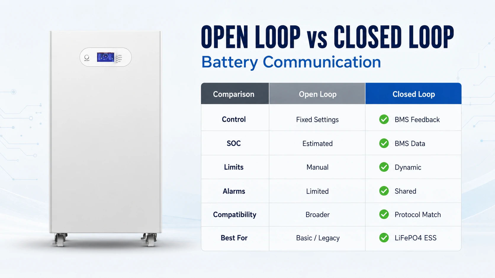
Open-loop battery systems operate from fixed inverter settings, while closed-loop systems use BMS feedback to update charge voltage, charge current, discharge current, SOC and alarms. Closed loop is usually preferable for modern LiFePO4 storage—but only when the battery, inverter, protocol, pinout and firmware have been validated together.
The most important point is that a CAN or RS485 port alone does not prove closed-loop compatibility. The two devices must understand the same data structure and respond correctly to changing battery limits.
What Is the Difference Between Open and Closed Loop Battery Communication?
Closed-loop systems provide real-time coordination and dynamic operating limits, while open-loop systems rely on fixed inverter parameters. Closed loop normally offers better battery visibility and control, but open loop may remain suitable when both manufacturers approve the configuration and conservative settings are available.
| Factor | Open-loop Communication | Closed-loop Communication |
|---|---|---|
| BMS-to-inverter data | None or monitoring only | Active battery data and limits |
| Inverter settings | Manually programmed | Automatically adjusted where supported |
| SOC source | Voltage or external shunt estimate | Usually reported by battery BMS |
| Charge current | Fixed maximum | Can change with temperature, SOC and cell condition |
| Discharge current | Fixed inverter limit | Can follow the BMS DCL |
| Alarm coordination | Battery may disconnect locally | BMS can warn or request stop before disconnecting |
| Compatibility | Works with more generic equipment | Requires matching protocols and firmware |
| Commissioning | More manual parameter entry | Easier after compatibility is confirmed |
| Communication failure risk | No communication dependency | Requires defined fail-safe behavior |
| Typical application | Lead-acid, simple systems, approved lithium retrofits | Modern LiFePO4, hybrid solar, backup and C&I ESS |
| Main risk | Incorrect fixed settings or poor SOC estimation | Protocol mismatch, bad cable or ignored limits |
Closed loop should not be marketed as a replacement for BMS protection. The internal BMS, contactors, breakers, fuses and temperature protections remain necessary even when inverter communication is operating correctly.
Planning a battery project? Send Avepower your inverter brand, exact model, firmware version, system voltage, battery quantity and required charge/discharge power. The engineering team can review the protocol, cable pinout and operating limits before production—helping reduce commissioning delays and on-site compatibility problems.
What Is Open and Closed Loop Communication in a Battery System?
Open-loop communication means the inverter controls the battery from manually configured limits without receiving operating instructions from the battery BMS. Closed-loop communication means the BMS sends battery status and allowable operating limits to a compatible inverter, which then adjusts charging or discharging in response.
In an open-loop system, the inverter normally relies on:
- Fixed charge voltage
- Fixed charge current
- Low-voltage cutoff
- Charge stages and timers
- External shunt-based SOC estimation
- User-programmed temperature or safety margins
The battery may still contain a fully functional BMS. “Open loop” does not mean “no BMS”; it means the BMS and inverter are not coordinating normal operation through a supported communication link.
In a closed-loop battery system, the BMS can send SOC, voltage, temperature, alarms and current limits to the inverter. The inverter uses those values to control power before the battery reaches a hard protection threshold.
For more background on local battery protection, see Avepower’s guide to the battery management system.
How Does Closed-Loop Battery Communication Work?
Closed-loop battery communication turns BMS measurements into operating limits for the inverter or power conversion system. The BMS measures individual cells and pack conditions, calculates safe limits, sends them over CAN or RS485, and expects the inverter to keep charging and discharging within those limits.
A typical control path is:
- Cell-monitoring circuits measure voltage and temperature.
- The BMS calculates SOC, fault status and safe operating limits.
- The master battery or BCU aggregates data from the battery bank.
- Data is transmitted to the inverter, PCS or system gateway.
- The inverter adjusts charging or discharging.
- The BMS continues monitoring the result and updates its requests.
A closed loop does not always require equal two-way conversation. In some implementations, the BMS continuously broadcasts limits while the inverter listens and acts. It is still considered closed-loop control because battery feedback changes the power converter’s behavior.
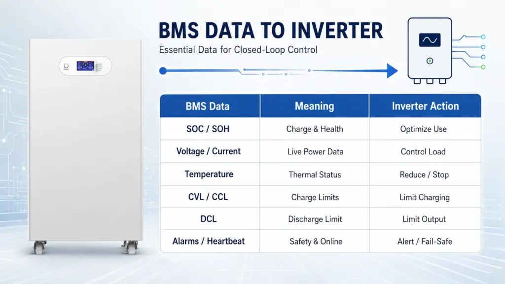
What Data Should the BMS Send to the Inverter?
A useful closed-loop connection should transmit more than pack voltage and SOC. At minimum, the integration should provide valid charge and discharge limits, operating status and communication health, because monitoring-only data cannot prevent the inverter from requesting more current than the battery presently accepts.
| BMS Data | Meaning | Typical Inverter Action |
|---|---|---|
| SOC | Estimated remaining charge | Start or stop charging, reserve backup capacity |
| SOH | Estimated battery condition | Maintenance and derating decisions |
| Pack voltage | Total DC voltage | Validate operating range |
| Pack current | Charge or discharge current | Monitor actual battery loading |
| Temperature | Cell or pack temperature | Reduce or stop charging/discharging |
| CVL | Charge Voltage Limit | Keep DC charge voltage below the requested limit |
| CCL | Charge Current Limit | Reduce charger or PV charge current |
| DCL | Discharge Current Limit | Limit inverter output or battery discharge |
| Charge enable | Permission to charge | Start or stop charging |
| Discharge enable | Permission to discharge | Start or stop inverter discharge |
| Alarm/fault code | Overvoltage, temperature or other fault | Derate, alarm or shut down |
| Heartbeat/status | Confirms the BMS is online | Continue operation or enter fail-safe mode |
Not every inverter supports every field. For example, one integration may display SOC but ignore DCL, while another may actively follow all three limits—CVL, CCL and DCL. Therefore, seeing battery data on the inverter screen is not sufficient proof that closed-loop control is working.
Avepower’s battery monitoring system guide explains how voltage, current, temperature, SOC, SOH and alarm data move between the battery, inverter and monitoring platform.
Need to Confirm Battery–Inverter Compatibility?
Send Avepower your inverter brand, exact model, firmware version, system voltage, battery quantity and required charge/discharge power. The engineering team can review the protocol, pinout and operating limits before production, helping installers, distributors and OEM customers reduce commissioning delays and compatibility risks.
Does CAN or RS485 Automatically Mean Closed-Loop Communication?
No. CAN and RS485 describe communication technologies, but they do not guarantee that the battery and inverter understand the same commands. Compatibility also depends on the connector pinout, bitrate, addressing, message identifiers, register map, protocol version, firmware and the control fields implemented by both devices.
| Term | What it Describes | What it Does Not Prove |
|---|---|---|
| CAN bus | Differential communication bus and frame transport | That two products use the same battery message map |
| RS485 | Differential serial electrical interface | That both devices use the same Modbus registers |
| Modbus RTU | Application protocol commonly used over RS485 | That the correct battery register map is supported |
| RS232 | Point-to-point serial interface, often used for service | That it can control the inverter |
| RJ45 | Connector format | The pinout, protocol or voltage level |
| “Pylon protocol” | A commonly supported battery protocol profile | Compatibility with every battery or firmware using that label |
How Should Closed-Loop Communication Be Configured?
Closed-loop commissioning should begin with verified manuals and end with a controlled response test. The installer must confirm that the inverter is receiving valid battery data and actively following current and voltage limits—not merely showing SOC on its display.
A practical sequence is:
- Record the battery and inverter model numbers and firmware versions.
- Confirm voltage and current compatibility before making connections.
- Obtain the approved communication protocol and pinout.
- Power down the battery and inverter according to their manuals.
- Set battery addresses and select the primary or master module.
- Connect inter-battery communication cables in the required order.
- Install CAN or RS485 termination where specified.
- Connect the master battery or BCU to the correct inverter BMS port.
- Select the correct lithium battery profile or protocol in the inverter.
- Start the battery network before the inverter if the manual requires it.
- Confirm SOC, voltage, temperature, CCL and DCL on the inverter.
- Perform a controlled charge and discharge test.
- Verify alarms and communication-loss behavior.
- Save the final settings, cable diagram and firmware versions.
For parallel battery banks, the inverter should normally receive one coordinated data source. The master battery or controller must aggregate capacity, current limits and alarms from all modules. Multiple uncoordinated BMS devices should not independently command the same inverter unless the manufacturer explicitly supports that architecture.
What Happens If Closed-Loop Communication Fails?
Communication-loss behavior is product-specific and must be tested before handover. Some inverters shut down immediately, while others alarm, apply a predefined limit or require manual reconfiguration. The safest assumption is that normal operation cannot continue until the manufacturer documents the intended fallback response.
After its inverter/charger has received CVL, CCL or DCL from a managed battery, loss of the battery connection triggers a BMS connection-lost alarm and shuts down the inverter/charger to protect the system.
A robust design should define:
- Communication timeout duration
- Inverter action after timeout
- Whether charging and discharging both stop
- Whether fixed open-loop settings remain stored
- Whether automatic recovery is allowed
- Alarm reporting to the user or EMS
- Local BMS disconnect behavior
- Restart and inspection procedure
Do not assume the system will automatically fall back to safe open-loop settings. If fallback is supported, configure those values according to both manufacturers’ documentation and test the transition during commissioning.
Can a Lithium Battery Operate Safely in Open-Loop Mode?
A lithium battery can operate in open-loop mode when both manufacturers allow it and the inverter is programmed with conservative battery-specific limits. However, the system loses dynamic BMS feedback, so accurate settings, independent protection, temperature control and periodic verification become more important.
An open-loop configuration should include:
- Manufacturer-approved charge voltage
- Conservative charge-current limit
- Correct low-voltage cutoff
- Suitable recharge or recovery voltage
- Disabled or correctly configured equalization
- Appropriate float settings for the battery chemistry
- Temperature-based charging restrictions
- External shunt monitoring where needed
- Functional internal BMS protection
- Correct breakers, fuses and cable sizing
There is no universal open-loop voltage table for every 48V LiFePO4 battery. Cell count, BMS thresholds, balancing strategy and manufacturer recommendations differ.
Open loop should not be used when:
- The inverter requires a managed battery
- The battery warranty requires approved communication
- The system depends on dynamic temperature derating
- High-voltage contactors require PCS communication
- Multiple battery racks need centralized current limits
- The manufacturer does not publish open-loop parameters
Calculation: Why Dynamic Discharge Limits Matter
Dynamic limits directly change the power available from a battery. Using an Avepower 48V 300Ah vertical battery as an example, the published standard discharge current is 157A and the maximum is 200A for up to 300 seconds. These ratings illustrate why an inverter must respect the battery’s current limit.
The approximate DC power is:
P=V×I
At the standard 157A discharge current:
48V×157A=7,536W≈7.54kW
At the 200A short-duration maximum:
48V×200A=9,600W=9.60kW
Now assume the BMS temporarily reduces the DCL to 60A because of temperature, SOC or cell imbalance. This 60A value is an illustrative engineering scenario, not a published product threshold:
48V×60A=2,880W=2.88kW
A 5kW load would ideally require at least:
5,000W÷48V=104.2A
Actual battery current would be higher after inverter losses. If the inverter receives a 60A DCL through closed-loop communication, it can limit output or raise an alarm according to its control design. In open-loop mode, it may continue requesting more than 104A until voltage falls or the internal BMS disconnects.
The relevant Avepower 48V 300Ah battery supports CAN, RS485 and RS232, but the exact closed-loop behavior still depends on the matched inverter protocol.
Avepower High-Voltage ESS Communication Example
High-voltage ESS projects require coordinated BMU, BCU and PCS communication because one fixed current value may represent tens of kilowatts. Avepower’s Netherlands project used a 345.6V, 314Ah, 108.5kWh system with six battery packs, a high-voltage BCU box and CAN-based monitoring.
The project’s rated current was 100A:
345.6V×100A=34.56kW
Its published maximum continuous discharge current was 200A:
345.6V×200A=69.12kW
This difference demonstrates why the PCS must distinguish rated current, temporary maximum current and any dynamic limit issued by the BCU. The system included cell-voltage detection, temperature sampling, SOC estimation, insulation monitoring and communication with the upper-level controller.
See the full 108.5kWh high-voltage ESS case study. The project data confirms the battery architecture and current ratings; the final PCS protocol and fail-safe logic must still be validated for each inverter integration.
Build a Battery System That Communicates Reliably
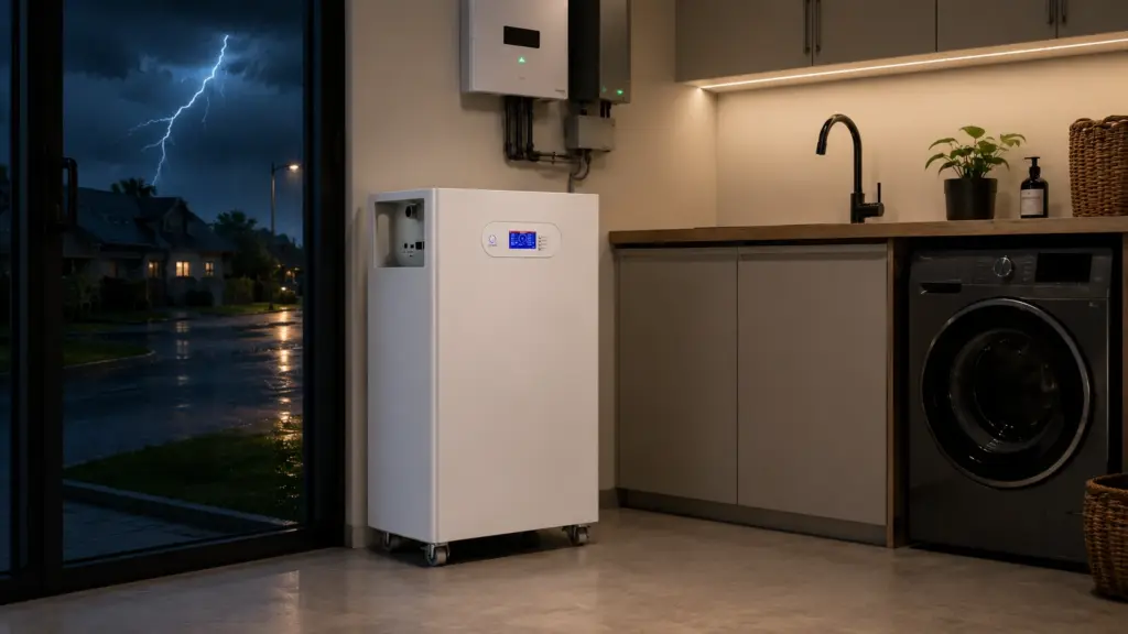
Avepower provides LiFePO4 battery systems with CAN, RS485 and RS232 communication, inverter matching and OEM/ODM protocol customization for residential and commercial energy storage projects.
How Do You Troubleshoot Battery Communication Failure?
Most battery communication failures come from the wrong port, incorrect cable pinout, protocol mismatch, network settings, firmware or multi-battery addressing. Troubleshooting should begin with documentation and live data rather than repeatedly changing voltage limits or replacing hardware without identifying the failed layer.
| Symptom | Likely Cause | Recommended Check |
|---|---|---|
| Inverter shows “No Battery” | Wrong BMS port or no battery power | Confirm BMS status and model-specific port |
| Battery appears but SOC is missing | Partial or wrong protocol mapping | Confirm protocol profile and firmware |
| SOC is displayed but current is not limited | Monitoring works but control fields are ignored | Check whether CCL and DCL are implemented |
| Communication works intermittently | Termination, noise, loose connector or wrong bitrate | Inspect cable, shielding, termination and network speed |
| One battery works but the full bank fails | Duplicate address or no master module | Check DIP switches and master/slave configuration |
| Charging stops at high SOC | CCL or CVL has fallen to zero/low value | Inspect cell voltage, temperature and BMS alarms |
| Battery disconnects under load | DCL ignored or inverter demand too high | Compare actual current with real-time DCL |
| Data values are unrealistic | Scaling or register-map mismatch | Verify protocol revision and units |
| Communication fails after an update | Firmware compatibility changed | Compare approved firmware versions |
| Bluetooth works but inverter does not | App monitoring is separate from inverter control | Check the wired CAN/RS485 connection |
A Bluetooth or WiFi app is not evidence of closed-loop inverter control. It may display battery information without transmitting any operating limits to the inverter.
When Should You Choose Open Loop or Closed Loop?
Choose closed loop for modern LiFePO4 systems when an approved battery–inverter combination is available and dynamic control has operational value. Choose open loop only when the manufacturers support it, correct fixed settings are available and the application does not depend on real-time BMS control.
Closed loop is normally the better choice for:
- Residential hybrid solar systems
- Whole-home backup systems
- High-power LiFePO4 batteries
- Multi-battery parallel banks
- Commercial and industrial ESS
- High-voltage battery systems
- Remote installations requiring detailed alarms
- Systems exposed to changing battery temperatures
Open loop may be reasonable for:
- Lead-acid battery systems
- Simple low-power installations
- Legacy inverters without BMS communication
- Temporary troubleshooting
- Approved lithium retrofits
- Systems using conservative limits and independent monitoring
Closed loop is not automatically better if the integration is untested. A reliable open-loop system with correct parameters can be safer than a supposed closed-loop system using the wrong protocol or cable.
Conclusion
The safest battery communication strategy is not simply “use CAN” or “choose closed loop.” It is to validate the complete battery–inverter combination, including voltage, protocol, pinout, firmware, dynamic limits, parallel-battery logic and communication-loss response before installation or bulk procurement.
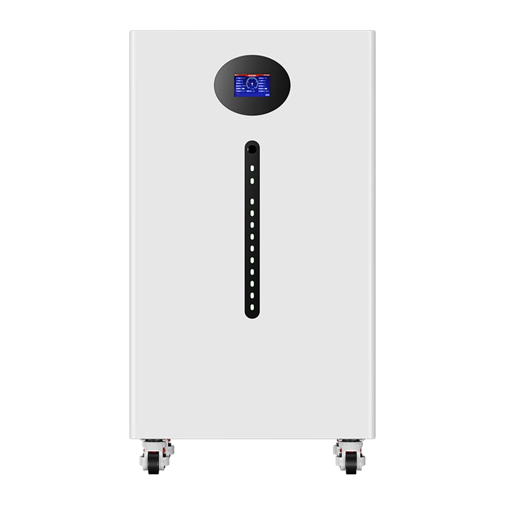
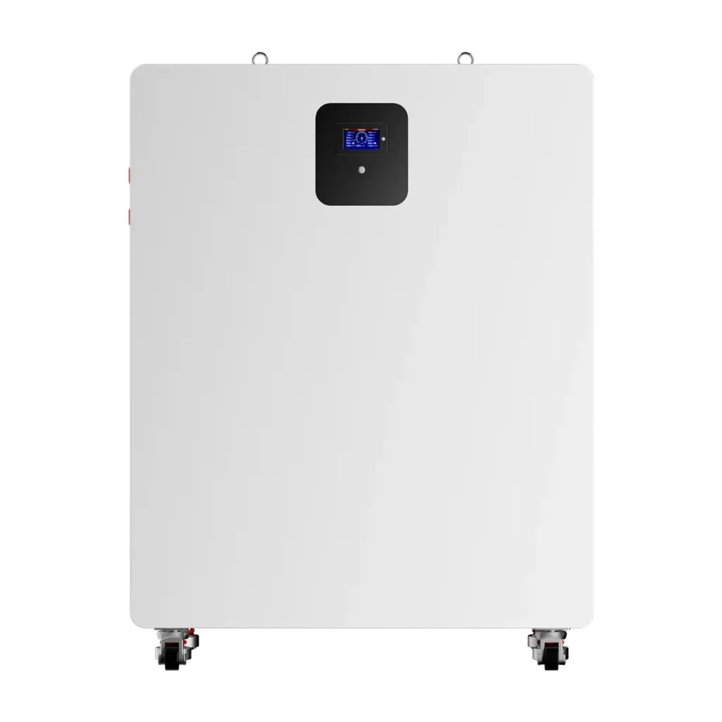
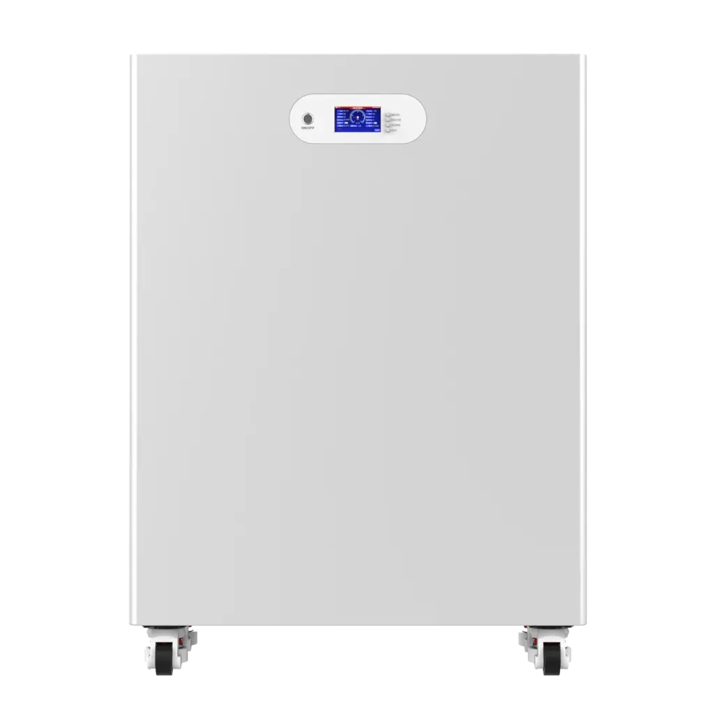
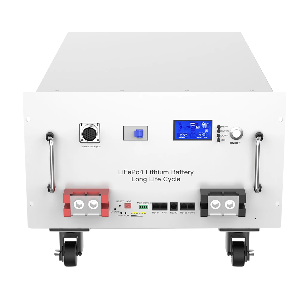
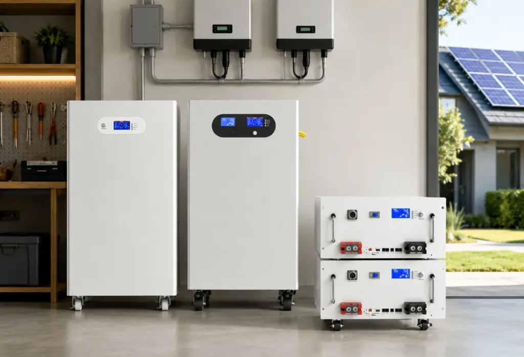
Avepower supplies LiFePO4 batteries with CAN, RS485 and RS232 options across vertical, rack-mounted, wall-mounted and stackable battery systems. Communication protocols, BMS settings and system parameters can also be matched through its OEM/ODM battery customization service.
Take Control of Your Energy with Avepower!
Reliable home solar battery solutions with OEM/ODM customization and in-house manufacturing, tailored to the needs of distributors, installers, and energy partners.
FAQ
True compatibility must be verified at six levels: electrical ratings, communication interface, connector pinout, network settings, application protocol and firmware behavior. A brand name or communication-port label is insufficient because compatibility may change between inverter models, regional versions and firmware releases.
No. Both devices must use the same CAN bitrate, pinout, message identifiers, data scaling, protocol version and firmware. A CAN connector alone only confirms that the hardware interface may be available.
Neither is universally better. CAN is widely used for real-time BMS control, while RS485 is commonly used with Modbus RTU or proprietary protocols. The best choice is the interface and protocol jointly supported by the exact battery and inverter models.
It can when the BMS and inverter support dynamic charge requests. 25%–40% faster charging in certain supported configurations, but this is manufacturer-specific data and should not be treated as a universal result.
It can reduce avoidable stress by communicating temperature, cell condition and charge/discharge limits before a hard BMS cutoff. Actual battery life still depends on chemistry, temperature, depth of discharge, charge rate, cell quality and system design.
The response depends on the inverter. Some systems shut down, while others alarm or apply fallback settings. The expected behavior must be documented and tested before commissioning.
Confirm that SOC and battery voltage are visible, then verify that the inverter responds when CCL or DCL changes. Also check alarm transmission and perform the manufacturer-approved communication-loss test.