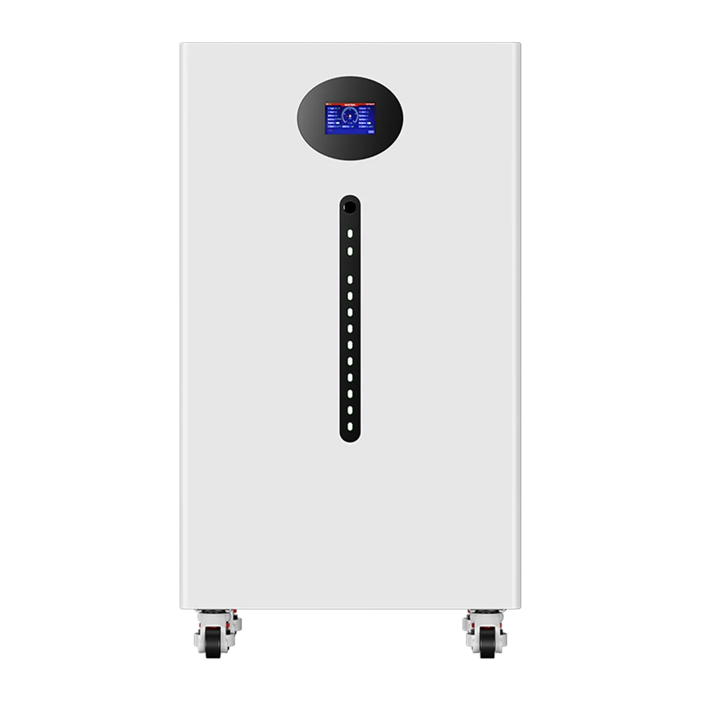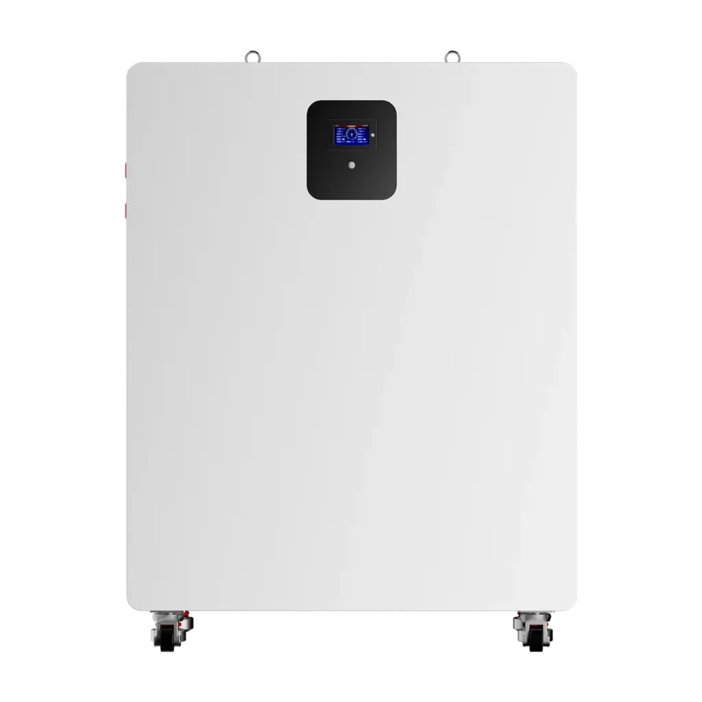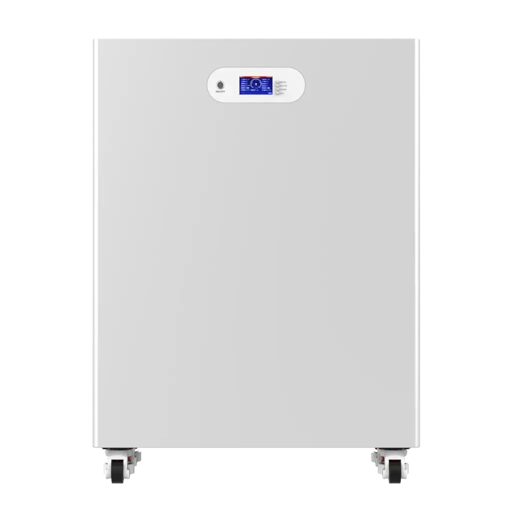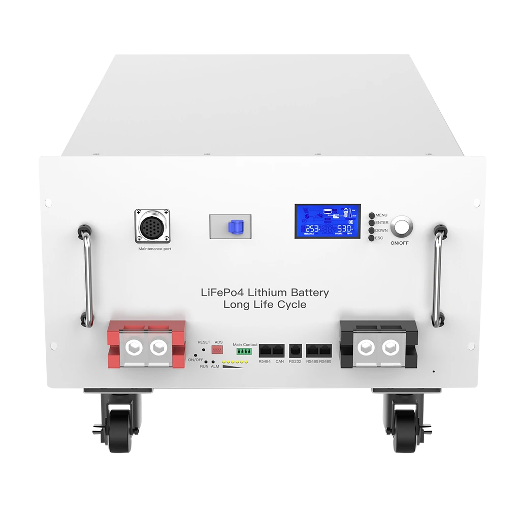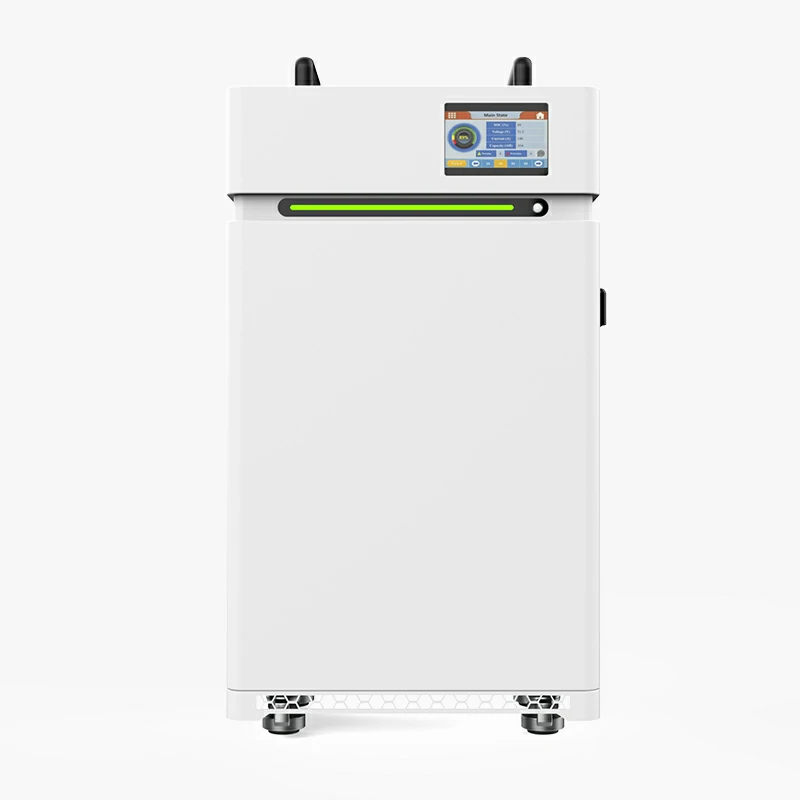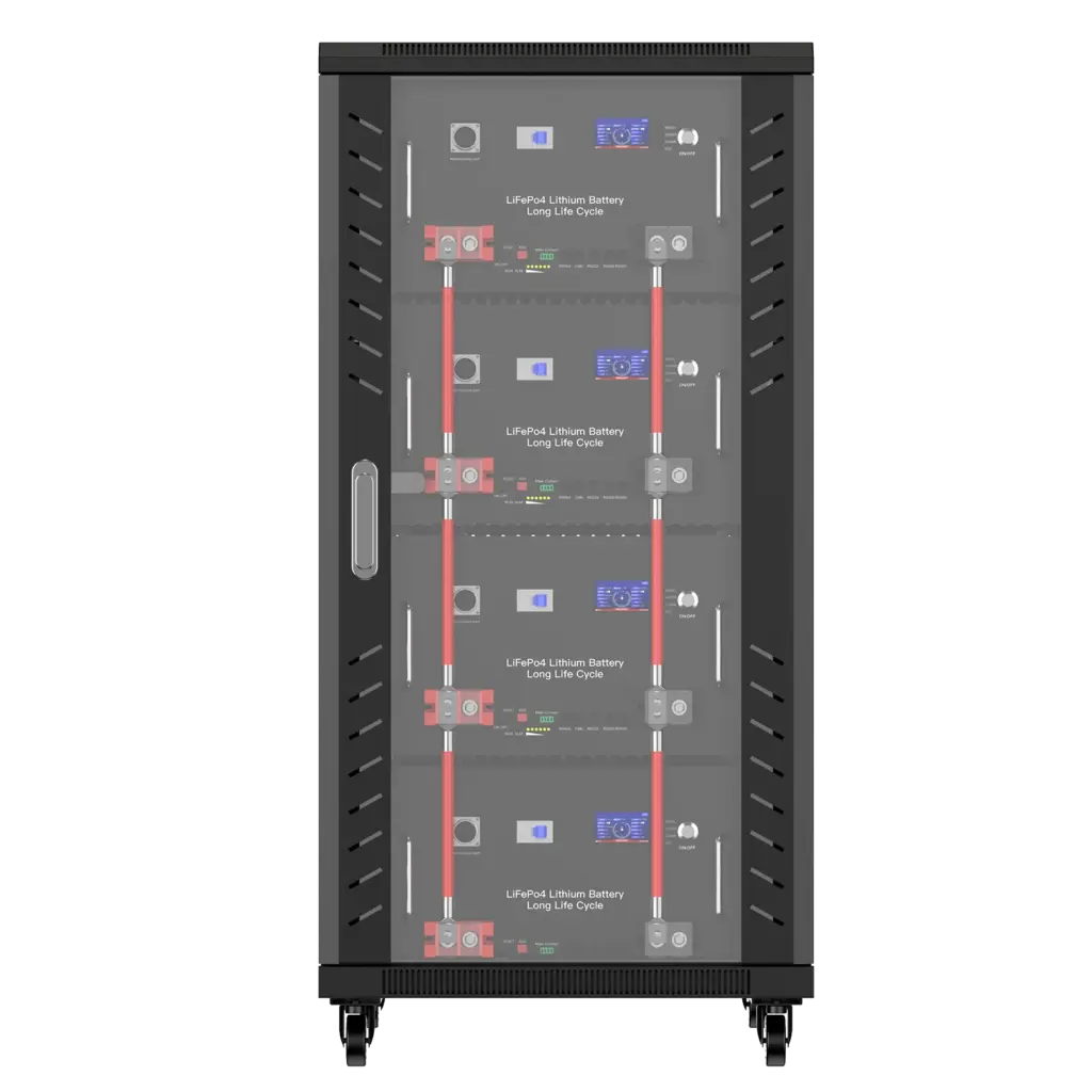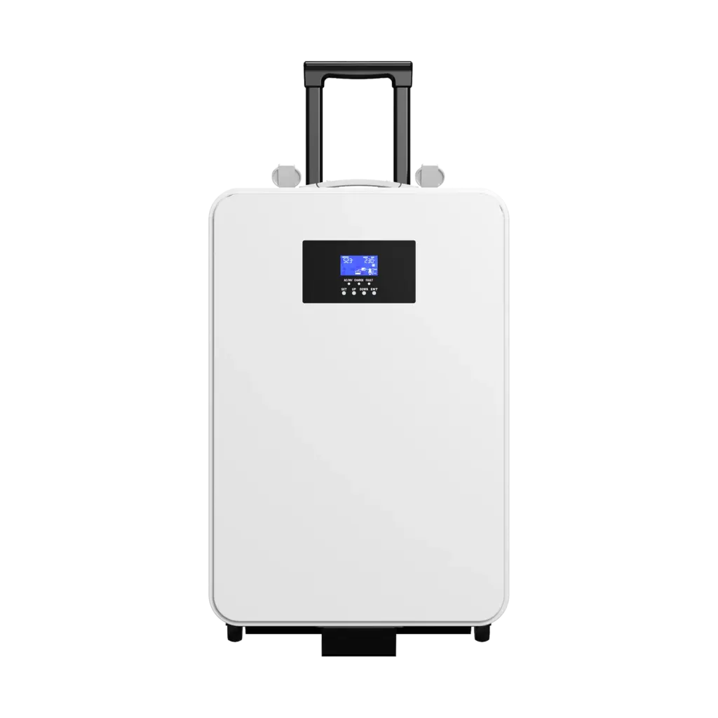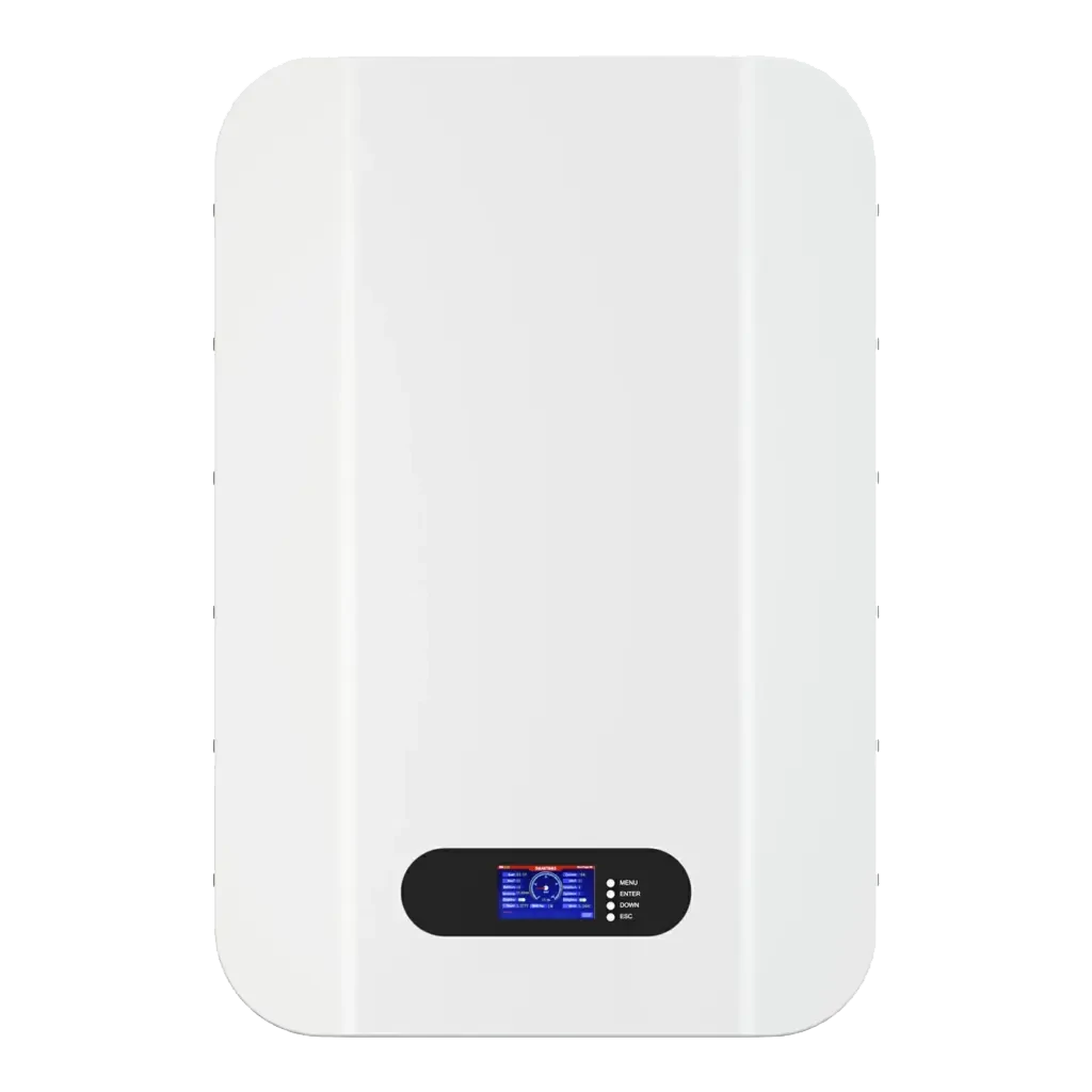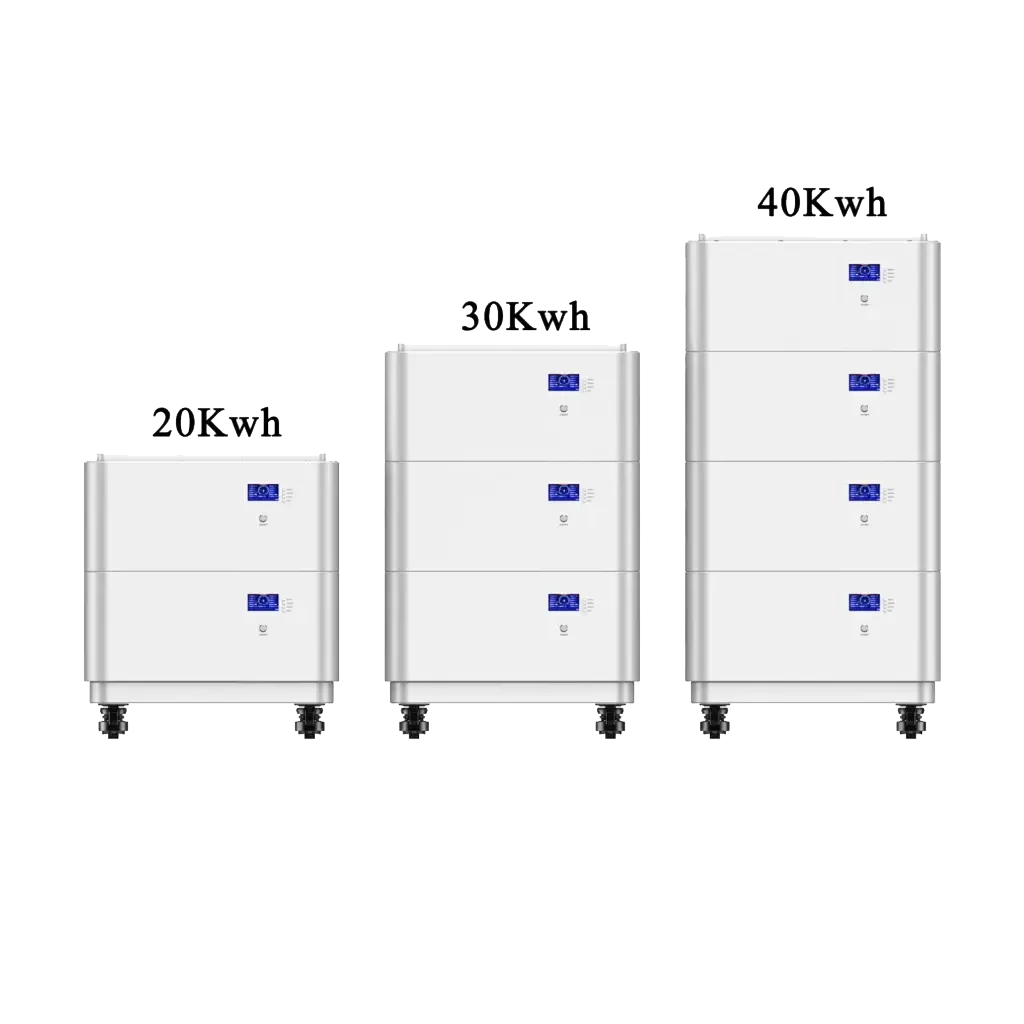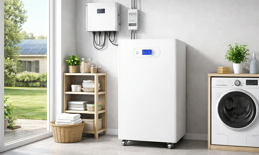

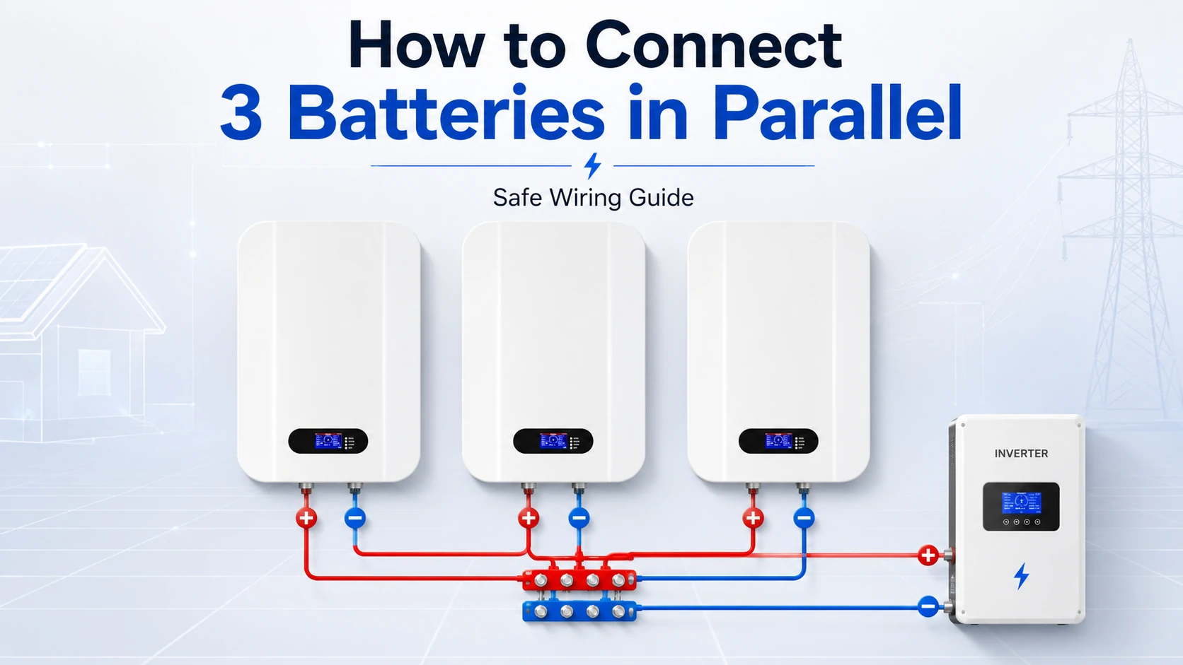
To connect three batteries in parallel, connect all three positive terminals to a common positive busbar and all three negative terminals to a common negative busbar. Use matched batteries, equal-length branch cables, individual positive-side protection and a main DC disconnect. Confirm voltage, polarity, BMS communication and manufacturer limits before energizing the bank.
A parallel connection keeps the system voltage the same while adding the amp-hour capacity and nominal energy of all three batteries. However, a safe and balanced installation requires more than simply linking positive to positive and negative to negative.
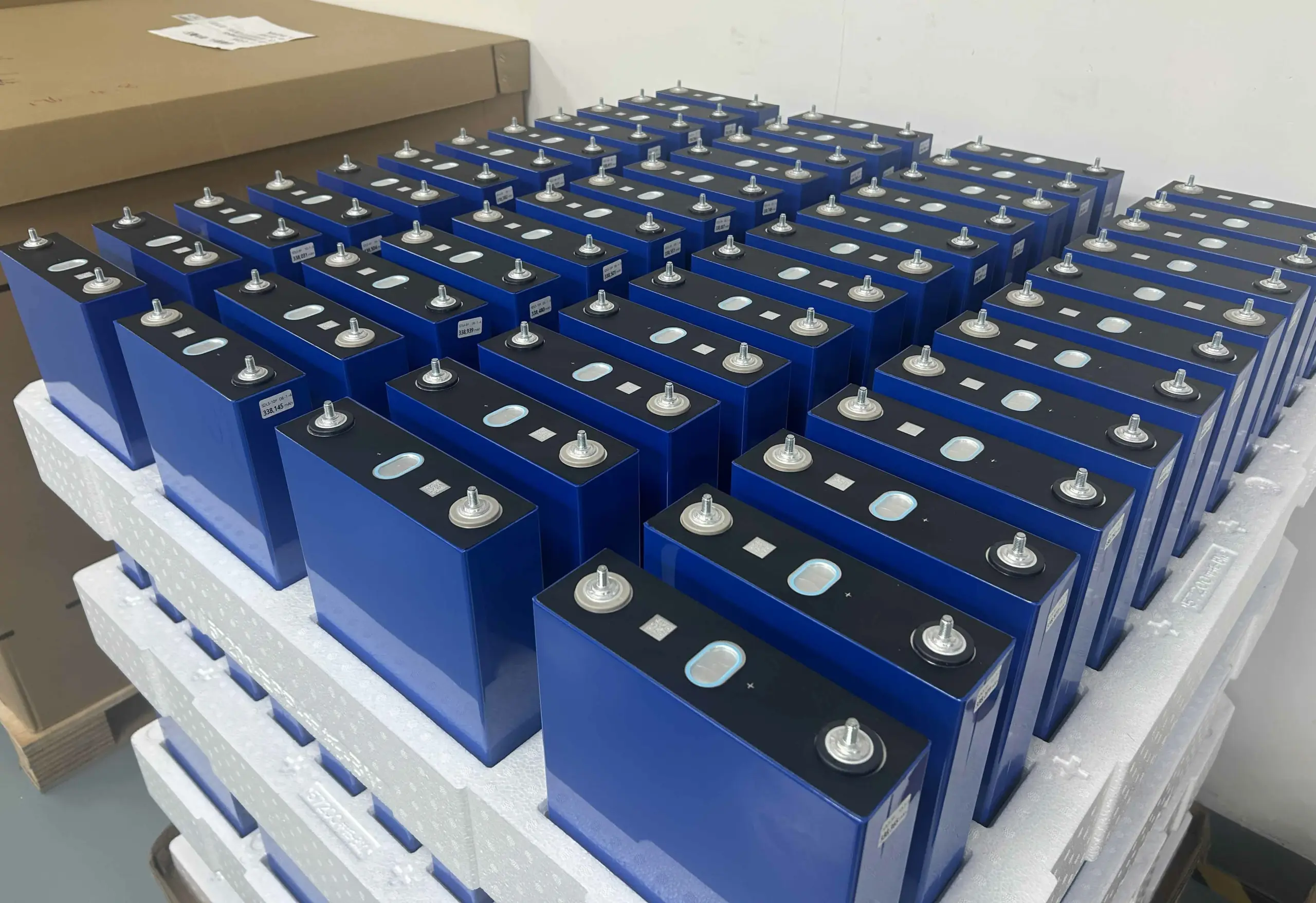
This guide applies primarily to complete 12V, 24V, 48V or 51.2V battery modules with an integrated BMS. It is not an assembly guide for paralleling bare lithium cells, damaged batteries or modules that the manufacturer has not approved for parallel operation.
What Happens When You Connect Three Batteries in Parallel?
Three matched batteries connected in parallel retain the voltage of one battery while their amp-hour capacity, nominal energy and potential current capability are combined. Runtime can increase substantially, but only when the charger, inverter, wiring, protection devices and BMS are designed for the larger bank.
The basic parallel formulas are:
- Bank voltage: voltage of one battery
- Bank capacity: Ah₁ + Ah₂ + Ah₃
- Nominal energy: voltage × total Ah ÷ 1,000
- Potential current limit: subject to the lowest system-level restriction
For example, three 12V 100Ah batteries produce:
| Parameter | One Battery | Three in Parallel |
|---|---|---|
| Nominal voltage | 12V | 12V |
| Capacity | 100Ah | 300Ah |
| Nominal energy | 1.2kWh | 3.6kWh |
| Number of battery modules | 1 | 3 |
Three 51.2V 100Ah modules produce a 51.2V, 300Ah bank with:
51.2V × 300Ah ÷ 1,000 = 15.36kWh
Parallel wiring does not convert three 12V batteries into 36V. That result would require a series connection. For a deeper comparison, see batteries in series vs parallel.
Planning a 3-Battery Parallel System?
Share your battery voltage, inverter model and required backup capacity. Avepower can help you evaluate battery compatibility, parallel quantity, communication protocol and recommended system configuration.
Can Any Three Batteries Be Connected in Parallel?
No. The safest approach is to use three batteries from the same manufacturer, model, chemistry, nominal voltage, capacity class, BMS generation and production batch. Their state of charge and measured terminal voltage should also meet the battery manufacturer’s specified range before connection.
The following compatibility check should be completed before any cables are installed.
| Battery Condition | Recommended? | Reason |
|---|---|---|
| Same model, voltage, capacity and chemistry | Yes | Best chance of balanced current sharing |
| Same model but different SOC | Not until balanced | Equalization current may flow between batteries |
| Same voltage but different Ah ratings | Usually no | Current and SOC may diverge |
| Same Ah but different brands | Usually no | BMS limits and charge profiles may differ |
| New battery with a heavily aged battery | Not recommended | Capacity and internal resistance are mismatched |
| LiFePO4 mixed with lead-acid | No | Different charge profiles and voltage behaviour |
| Damaged or swollen battery | No | Unsafe and unsuitable for service |
| Modules not approved for paralleling | No | May violate BMS or warranty limits |
| 48V module mixed with 51.2V module | No | Nominal and operating ranges may not match |
Why Does Voltage Matching Matter?
Voltage matching limits the uncontrolled equalization current that can flow when the batteries are first joined. Even a small voltage difference can produce substantial current because lithium batteries and short battery cables usually have very low combined resistance.
The approximate equalization current can be illustrated by:
Current = voltage difference ÷ total circuit resistance
Suppose two batteries differ by 0.20V and the complete connection path has only 0.005Ω of resistance:
0.20V ÷ 0.005Ω = 40A
This is a simplified calculation, but it shows why batteries should be individually charged, rested and measured before their terminals are joined.
Do not rely only on displayed SOC. SOC estimation can differ between BMS units, especially after storage, incomplete charge cycles or firmware resets. Measure actual terminal voltage with a suitable meter and follow the manufacturer’s commissioning process.
Build a Reliable Parallel Battery System
Tell Avepower how many batteries you need, which inverter you use and how much backup capacity your project requires. Our engineering team will help evaluate battery compatibility, communication protocols, current limits and expansion options.
What Is the Best Wiring Layout for Three Batteries in Parallel?
A positive and negative busbar with equal-length cables to each battery is generally the clearest and most scalable layout. A correctly designed diagonal connection can also work for three batteries, but connecting the inverter and charger to the same end of a daisy-chained bank creates a less balanced current path.
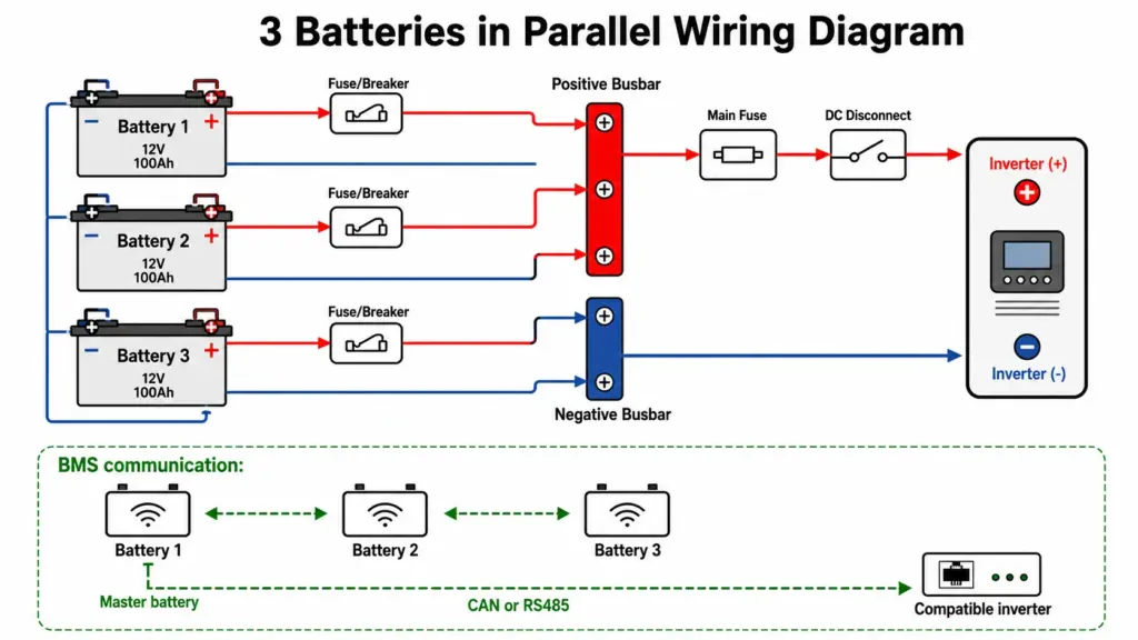
Recommended Busbar Layout
Battery 1 (+) ── Fuse/Breaker ──┐
Battery 2 (+) ── Fuse/Breaker ──┼── Positive Busbar ── Main Fuse ── DC Disconnect ── Inverter (+)
Battery 3 (+) ── Fuse/Breaker ──┘

Battery 1 (-) ──────────────────┐
Battery 2 (-) ──────────────────┼── Negative Busbar ────────── Inverter (-)
Battery 3 (-) ──────────────────┘

BMS communication:
Battery 1 ↔ Battery 2 ↔ Battery 3
Master battery ── CAN or RS485 ── Compatible inverter
Busbar vs Diagonal vs Single-End Wiring
| Wiring Method | Current Balance | Installation Cclarity | Expansion | Recommendation |
|---|---|---|---|---|
| Equal-length cables to busbars | Very good | Excellent | Easy | Preferred for professional systems |
| Positive from one end, negative from the other | Generally good for three units | Good | Moderate | Acceptable when approved |
| Load connected to the same end | Poorer | Simple | Limited | Avoid for high-current banks |
| Unequal branch cables to a common point | Unpredictable | Poor | Poor | Not recommended |
Busbar ratings must cover the maximum expected continuous current, short-duration current and fault-current requirements. The busbar should also have suitable insulation, terminal spacing, covers and DC-rated hardware.
Need Batteries Designed for Parallel Expansion?
Avepower LiFePO4 battery systems support scalable configurations, CAN/RS485 communication and compatibility with multiple inverter brands. Choose the right capacity for residential, off-grid or small commercial projects.
What Equipment Is Needed to Connect Three Batteries in Parallel?
A professional installation normally requires matched battery modules, equal-resistance branch cables, properly rated busbars, individual branch protection, a main fuse or breaker, a DC disconnect, insulated tools, a torque wrench, a voltmeter and any required BMS communication cables or addressing accessories.
Prepare the following before installation:
- Three manufacturer-approved matching batteries
- Positive and negative DC busbars
- Equal-length positive branch cables
- Equal-length negative branch cables
- Correctly crimped, matching cable lugs
- One approved fuse or DC breaker for each positive branch
- Main battery-bank fuse or DC breaker
- Lockable or accessible DC disconnect
- DC-rated inverter cables
- BMS communication cables
- Termination resistors where specified
- Insulated hand tools
- Calibrated torque wrench
- True-RMS digital multimeter
- DC clamp meter for commissioning
- Terminal covers and warning labels
- Manufacturer wiring diagram and inverter manual
Cable lugs, mating surfaces and tightening torque affect branch resistance.
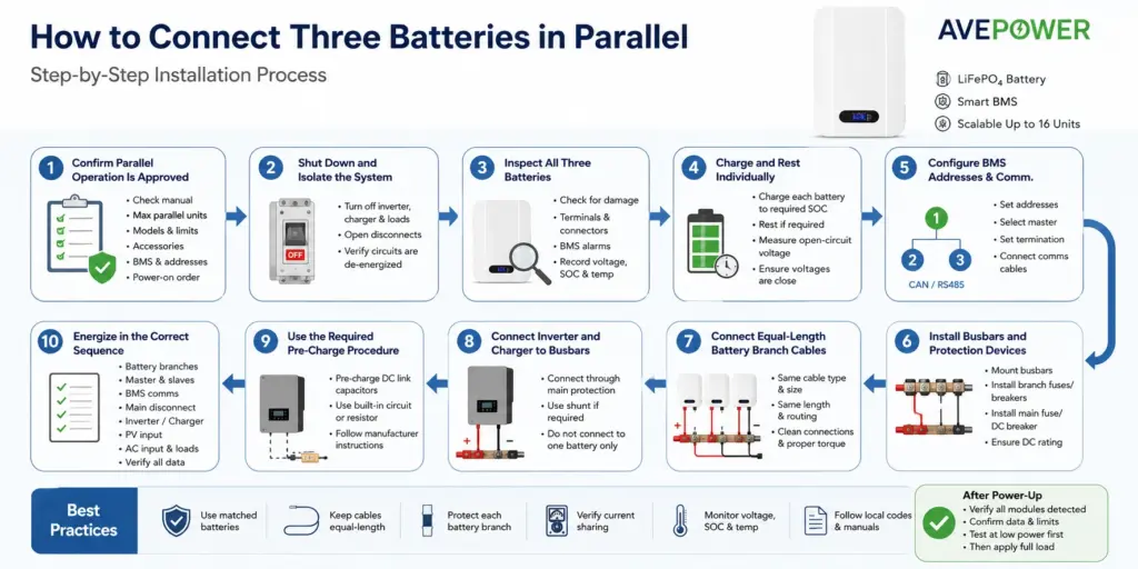
How Do You Connect Three Batteries in Parallel Step by Step?
Isolate every energy source, confirm the three batteries are compatible, bring them to the manufacturer’s required voltage range, install equal-length protected branches to common busbars, configure the BMS network and then commission the system at low power before applying the full load.
Step 1: Confirm Parallel Operation Is Approved
Check the battery manual for:
- Maximum number of parallel modules
- Permitted battery models
- Charge and discharge limits
- Required accessories
- Fuse or breaker recommendations
- BMS communication method
- Address or DIP-switch sequence
- Master-battery selection
- Firmware requirements
- Required power-on order
Do not assume three batteries can be paralleled merely because their labels show the same nominal voltage.
Step 2: Shut Down and Isolate the System
Turn off the inverter, solar charger, AC charger and all DC loads. Open the battery disconnects and verify that the relevant circuits are de-energized.
Stationary lithium battery installations should follow applicable local electrical and fire requirements. IEC 62485-5 addresses safety during installation, use, inspection and maintenance of stationary lithium-ion batteries, while national requirements may impose additional rules.
Step 3: Inspect All Three Batteries
Confirm that none of the modules has:
- Physical impact damage
- Swelling or enclosure distortion
- Corroded terminals
- Loose output connectors
- Active BMS alarms
- Abnormal temperature
- Water ingress
- An unknown maintenance history
Record each battery’s model, serial number, firmware, cycle count, SOC, terminal voltage and temperature where that information is available.
Step 4: Charge and Rest the Batteries Individually
Bring each battery to the state of charge specified by its manufacturer. After charging, allow the modules to rest if required and measure their open-circuit voltage using the same meter.
Do not connect a fully charged module directly to a substantially discharged module. The batteries may attempt to equalize before the inverter or charger is even switched on.
Step 5: Configure BMS Addresses and Communication
Set the battery addresses, master/slave selection and termination according to the battery manual. Do this before closing the high-current branch protection if the product permits configuration while isolated.
Parallel home batteries often use one communication path between modules and another path from the master battery to the inverter. The interface may be CAN or RS485, but electrical compatibility alone does not guarantee that the message protocol, pinout or firmware is compatible. See the battery communication and BMS protocol guide for more detail.
Step 6: Install the Busbars and Protection Devices
Mount the positive and negative busbars in a protected enclosure or approved compartment. Install the individual positive fuse or breaker for each battery as close to the source as the manufacturer and local rules require.
Add a main fuse or DC breaker between the positive busbar and inverter circuit. All protection equipment must be DC rated for the system voltage, expected current and available fault current.
Step 7: Connect Equal-Length Battery Branch Cables
Route each battery to the busbars using cables with:
- The same conductor material
- The same cross-sectional area
- The same positive-cable length
- The same negative-cable length
- Matching lugs
- Comparable bends and routing
- Clean contact surfaces
- Manufacturer-specified torque
The positive and negative cables do not necessarily have to be equal to each other, but each corresponding branch should present an equivalent total resistance.
Step 8: Connect the Inverter and Charger to the Busbars
Connect the system positive cable through the main protection and disconnect equipment. Connect the system negative cable to the negative busbar or approved shunt arrangement.
Do not place the inverter connection directly on Battery 1 while Batteries 2 and 3 are connected through progressively longer jumpers. That arrangement makes Battery 1’s current path shorter and can cause it to work harder.
Step 9: Use the Required Pre-Charge Procedure
Many inverters contain large DC-link capacitors. Connecting a charged battery bank directly to an uncharged capacitor bank can create a visible spark or a high inrush-current event.
Use the inverter or battery manufacturer’s approved pre-charge procedure, built-in pre-charge circuit or specified resistor device. Never improvise a pre-charge method on a live high-current system.
Step 10: Energize the Bank in the Correct Sequence
Follow the product-specific sequence for:
- Battery branch breakers or switches
- Master battery
- Slave batteries
- BMS communication
- Main battery disconnect
- Inverter or charger
- Solar input
- AC input and loads
After power-up, verify that the inverter detects the expected number of modules and receives valid SOC, voltage, current, temperature and charge/discharge limits.
How Should Cable and Fuse Sizes Be Calculated?
Cable and protection sizing must be based on the maximum operating current, conductor installation conditions, permitted voltage drop, BMS limits and available fault current—not merely the average current divided by three. The main cable carries the full bank current, while each branch must safely carry its possible module current.
A useful first estimate for inverter DC current is:
DC current = AC output power ÷ battery voltage ÷ inverter efficiency
For a 6kW inverter operating from a 51.2V battery bank at an assumed 93% efficiency:
6,000W ÷ 51.2V ÷ 0.93 = approximately 126A
With ideal sharing across three batteries:
126A ÷ 3 = approximately 42A per battery
However, this does not mean each branch only needs to be designed for 42A. The branch circuit may need to carry significantly more current when:
- One battery is offline
- Branch resistance is unequal
- One BMS limits its output
- The inverter produces a surge
- Charging current is uneven
- A fault causes reverse current from the other batteries
The final conductor and fuse ratings must therefore follow the battery, inverter and protection-device specifications as well as applicable electrical rules.
How Do You Charge Three Batteries Connected in Parallel?
Charge the three-battery bank at the voltage specified for one battery, because parallel wiring does not increase voltage. Set the total charge-current limit within the battery-bank, BMS, charger and cable ratings, and confirm that current is shared acceptably across all three modules.
For three identical 51.2V batteries, the charger still uses the approved charge-voltage profile for a 51.2V battery system. It does not use three times the voltage.
The theoretical bank charge-current limit may be the sum of the three individual limits, but the usable setting may be lower because of:
- Inverter-charger output limits
- Battery manufacturer recommendations
- Branch cable and connector ratings
- Busbar ratings
- Main fuse rating
- Temperature derating
- BMS communication limits
- Desired battery life
- Local installation requirements
In a closed-loop system, the inverter should follow the charge-voltage limit, charge-current limit and enable signals sent by the battery BMS. In an open-loop system, the installer must configure conservative voltage and current values from the battery documentation.
For a related two-module procedure, see how to charge two batteries in parallel.
Example: Three 5.12kWh Avepower Batteries in Parallel
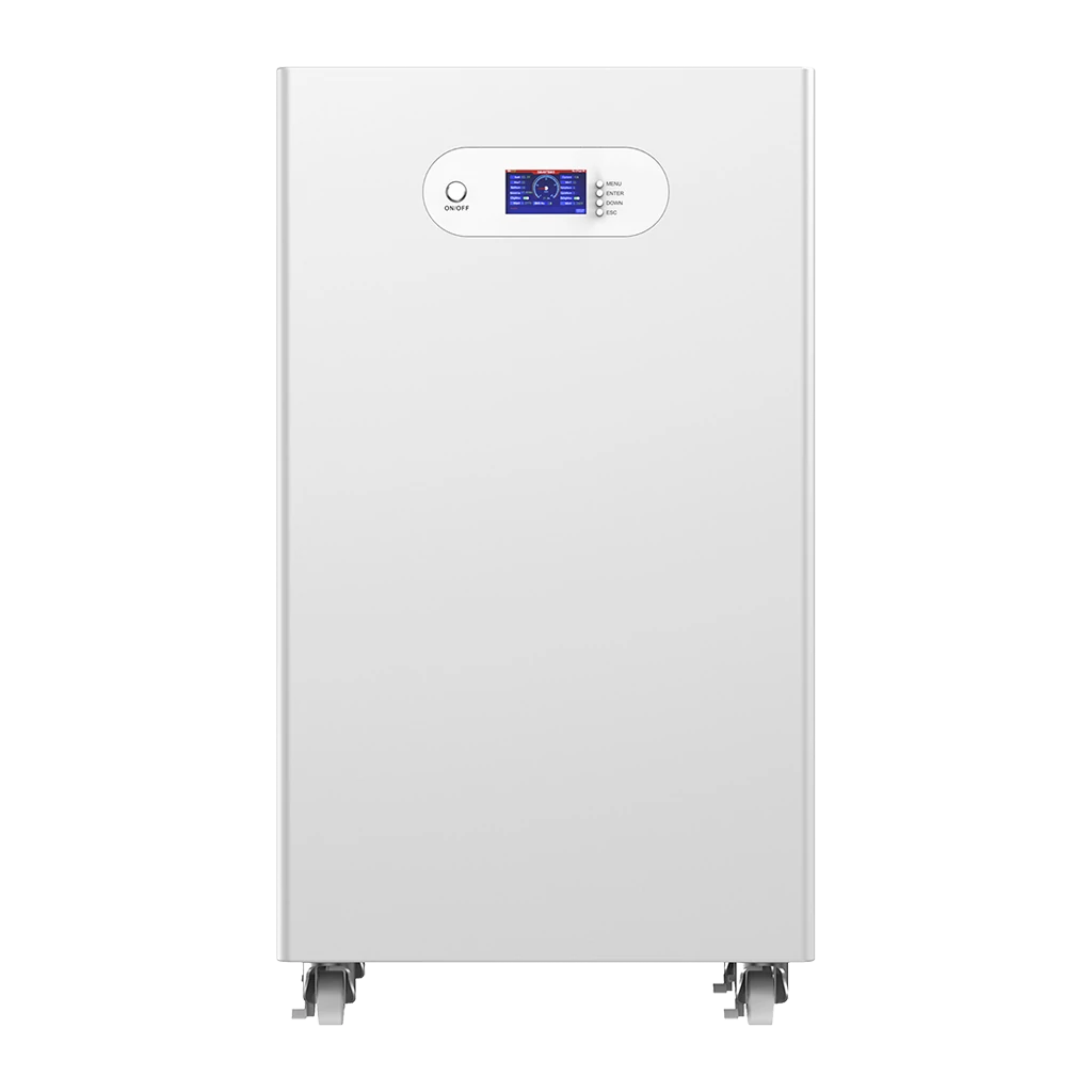
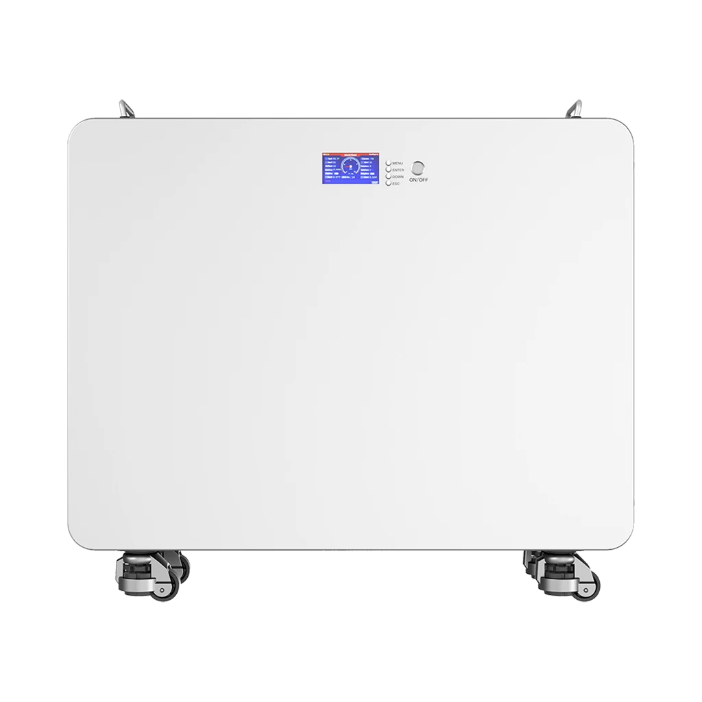
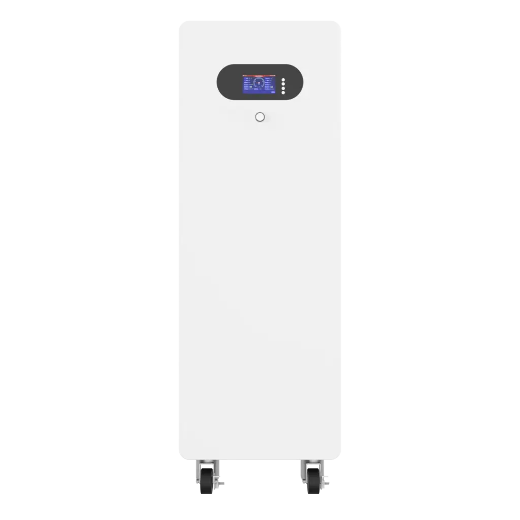
Three matched Avepower 51.2V 100Ah wall-mounted batteries would form a nominal 51.2V, 300Ah, 15.36kWh battery bank. The product platform supports parallel expansion, but the inverter, cables, busbars, branch protection, communication protocol and system settings must still be engineered for the three-module configuration.
The Avepower 5.12kWh wall-mounted battery is specified with:
- 51.2V nominal voltage
- 100Ah capacity
- 5.12kWh nominal energy
- 100A maximum continuous charge current
- 100A maximum continuous discharge current
- Up to 16 units in parallel
- LiFePO4 chemistry
- Integrated BMS
- 8,000+ cycles at 80% depth of discharge as published on the product page
These are product-level values, not permission to operate a three-module bank at 300A without checking every other system component.
Three-Battery Bank Calculation
| Parameter | Calculation | Result |
|---|---|---|
| Nominal voltage | 51.2V | 51.2V |
| Total capacity | 100Ah × 3 | 300Ah |
| Nominal energy | 5.12kWh × 3 | 15.36kWh |
| Published module discharge limit | 100A each | System-dependent combined limit |
| Number of batteries | 3 | Within published 16-unit platform limit |
If the system uses 80% of nominal energy and the inverter operates at an assumed 93% efficiency, the estimated AC energy is:
15.36kWh × 0.80 × 0.93 = 11.43kWh
For a steady 1.5kW load:
11.43kWh ÷ 1.5kW = approximately 7.6 hours
This is a planning estimate rather than a guaranteed runtime. Actual performance changes with temperature, inverter standby consumption, load variation, battery age, BMS reserve settings, cable losses and usable depth of discharge.
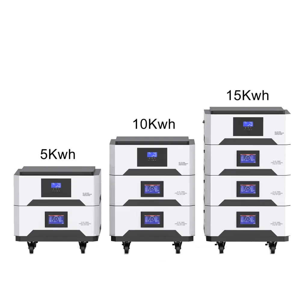
For installers who need modular capacity options, Avepower also offers 5kWh, 10kWh and 15kWh stackable solar batteries with CAN, RS485 and RS232 communication and published support for parallel expansion.
Planning a Three-Battery Parallel System?
Send Avepower your inverter model, required storage capacity, maximum load and installation market. Our engineering team can help verify battery configuration, BMS communication, current limits and parallel expansion requirements.
Build a Safer and More Reliable Battery Bank
Send us your inverter model, load power, required runtime and project quantity. Our engineering team will help you confirm battery capacity, wiring architecture, current limits and communication settings.
How Can You Tell Whether the Three Batteries Are Sharing Current Correctly?
A properly commissioned bank should show similar branch currents when the batteries have comparable SOC, temperature and health. Exact equality is unrealistic, but one battery should not repeatedly carry most of the load or remain almost idle during steady charging and discharging.
Use a DC clamp meter or battery monitoring interface to record:
- Current from Battery 1
- Current from Battery 2
- Current from Battery 3
- Individual battery voltage
- Individual SOC
- Battery temperature
- BMS alarms
- Total bank current
Illustrative Current-Sharing Test
Assume the inverter is drawing 120A.
| Battery | Expected Approximate Current | Example Acceptable Observation | Example Problem |
|---|---|---|---|
| Battery 1 | 40A | 39A | 65A |
| Battery 2 | 40A | 41A | 35A |
| Battery 3 | 40A | 40A | 20A |
A small variation may be normal. A persistent large difference requires investigation.
Check:
- Branch cable lengths
- Cable cross-sections
- Lug crimp quality
- Terminal torque
- Fuse and breaker contact resistance
- Battery temperature
- SOC alignment
- BMS address settings
- Communication termination
- Battery state of health
A battery monitoring system can help track voltage, current, temperature, SOC, alarms and communication status, but it does not replace correct wiring or individual branch testing.
Why Are Three Parallel Batteries Not Charging or Discharging Equally?
Unequal current is usually caused by different cable resistance, connection resistance, battery temperature, SOC, capacity, internal resistance or BMS limits. Begin with the physical current path, then check battery data and communication rather than assuming that the battery with the lowest SOC is defective.
Do not repeatedly reset a BMS without finding the cause. A reset may temporarily restore output while leaving an overcurrent, cell-voltage, temperature or communication problem unresolved.
What Happens If One of the Three Batteries Shuts Down?
If one battery disconnects, the remaining two modules may suddenly carry the full inverter or charger current. The system must therefore be designed so that loss of one branch does not overload the remaining batteries, their cables, connectors, BMS units or protection devices.
Consider the earlier 126A inverter-current example:
- With three batteries online: approximately 42A each under ideal sharing
- With two batteries online: approximately 63A each
- With one battery online: the remaining module could be asked for the full 126A
Whether operation continues safely depends on the battery’s continuous and surge-current limits. A properly integrated closed-loop system may reduce inverter power when the available battery count or discharge-current limit changes.
This is one reason the theoretical sum of three battery current ratings should not automatically be used as the inverter setting.
When Should You Not Connect Three Batteries in Parallel?
Do not parallel batteries when their nominal voltage, chemistry, BMS rules or charge profiles differ; when a module is damaged or substantially aged; when the manufacturer prohibits parallel operation; or when the installation lacks correctly rated wiring, protection, isolation and communication equipment.
Stop the project and seek manufacturer or qualified installer guidance when:
- Battery manuals conflict
- Parallel limits are unknown
- One battery has a different firmware generation
- The modules use incompatible communication protocols
- Terminal voltage cannot be brought into the required range
- A battery has recurring cell imbalance
- One module has a significantly different cycle count or capacity
- DC fault-current ratings are unknown
- The inverter requires a higher battery voltage rather than more capacity
- Local rules require a listed complete system
- The installation would expose live terminals
- No approved disconnect or overcurrent protection can be installed
High-voltage battery towers should not be treated as large low-voltage modules. Their series architecture, high-voltage control box, insulation monitoring, contactors and pre-charge system require a manufacturer-engineered configuration.
Avepower’s low-voltage lithium battery solutions are the more relevant category when a project needs parallel capacity expansion at 12V, 24V, 48V or 51.2V.
How Should a Three-Battery Parallel Bank Be Maintained?
Inspect the bank periodically for loose or heated terminals, branch-current imbalance, BMS alarms, unusual SOC divergence and changes in battery temperature. Compare readings with the commissioning baseline so that gradual connection resistance or battery degradation can be identified before it causes repeated shutdowns.
Build a Three-Battery System Around Verified Compatibility
Connecting three batteries in parallel can provide longer backup time and scalable storage without changing the nominal system voltage. Reliable performance, however, depends on matched batteries, equal-current paths, correctly rated DC protection, compatible BMS communication and documented commissioning—not only on terminal polarity.
Avepower provides wall-mounted, rack-mounted, vertical and stackable LiFePO4 battery systems for installers, distributors and OEM/ODM energy-storage projects. Supported platforms offer scalable parallel configurations, CAN/RS485/RS232 communication options and inverter-matching assistance. Explore Avepower home energy storage solutions or request a technical review of your battery count, inverter model, required runtime and communication protocol before finalizing the system.
Take Control of Your Energy with Avepower!
Reliable home solar battery solutions with OEM/ODM customization and in-house manufacturing, tailored to the needs of distributors, installers, and energy partners.
FAQ
Yes. Three matched 12V batteries connected positive-to-positive and negative-to-negative remain a 12V bank. Three 100Ah batteries provide 300Ah of nominal capacity, subject to their condition and usable depth of discharge.
Connect the inverter to properly rated positive and negative busbars supplied by equal-resistance battery branches. A diagonal connection can be acceptable when specified, but avoid taking both inverter conductors from the same end of a daisy-chained bank.
For many lithium battery systems, each positive battery branch requires individual overcurrent protection, and the main positive cable also requires protection. The exact fuse type, current rating and location must follow the battery manual and applicable electrical rules.
It is generally not recommended unless the manufacturer has explicitly validated that combination. Different capacities and internal resistances can lead to unequal current, different SOC behaviour and unexpected BMS shutdowns.
Adding a new battery may create capacity and resistance mismatches. Test the existing batteries and follow the manufacturer’s expansion policy. Some systems allow later expansion under defined conditions, while others require matched-age modules.
Nominal energy triples when three identical batteries are added, but usable runtime is affected by depth of discharge, inverter efficiency, temperature, load variation, standby consumption, battery age and BMS reserve settings.
A busbar is not the only technically possible arrangement, but it usually provides the clearest method for creating equal branch paths, adding individual protection, measuring current and expanding or servicing the system later.